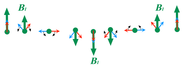
In a Q&A long, long ago, we discussed the difference between linear and circularly polarized RF coils in their use in transmission of the B1 field. In brief, the sinusoidal fluctuation of the transmit RF field B1 (green arrow) can be decomposed into two components each half as large: a component rotating in the same direction as nuclear precession (B1+) and a component rotating in the opposite direction (B1−). The B1+ subfield is responsible for tipping the nuclear magnetization. The B1− subfield and rotates opposite the spin system, generating only heat via induced electrical currents but having no effect on nuclei. The example below shows a linearly polarized B1 demonstrating equal and opposite B1+ and B1− components. In the modern era, nearly all transmit RF coils are circularly polarized, meaning (ideally) that B1+ = B1 and B1− = 0.
The term B1+rms refers to the "root mean square" value of B1+ averaged over a period of 10 seconds. B1+peak values may also be used. B1+rms can be thought of as a supplemental metric to SAR for controlling RF power deposition. Most modern scanners report this value along with SAR for each sequence, but scanners produced before 2013 will probably not. B1+rms is a more precise exposure metric because it depends primarily on the scanner and sequence and less on the patient than SAR.

Definition of B1+rms as illustrated for a simple sine wave. Because the wave has equal positive and negative portions, the simple average B1+avg is meaningless and always equals zero over any complete cycle. By squaring the B1+(t) amplitude at each point before summing over time interval T the root mean square produces a positive value. For a sine wave it can be shown by simple calculus that the B1+rms = B1+peak ÷ √2, or approximately 0.707 x B1+peak.
The International Electrotechnical Commission (IEC) describes a method by which manufacturers may calculate B1+ using the principle that B1+ scales linearly with voltage supplied to the transmitter. However, because each patient presents a different electronic load to the RF coil, the voltage required to attain a given flip angle must be empirically determined. This calibration occurs during pre-scan, where 1 ms rectangular pulses of different amplitude are tested until the reference transmitter voltage (Vref) to achieve a perfect 180º-pulse is determined. Once Vref is known, the magnitude of the B1+ field for any other transmitter voltages can be easily calculated.
As shown in a prior Q&A, SAR is directly proportional to (B1+)². The advantage of using B1+rms over SAR is that B1+rms can be directly calculated by measuring transmitter voltages producing the incident RF irradiation. Because B1+rms only depends on flip angle, it is independent of Bo (main) field strength (unlike SAR that is proportional to Bo²).
It should be noted that actual B1 and B1+ vary by location inside the subject and are thus determined as spatially averaged values within an axial center slab. The error in this estimation may be substantial, particularly if an implant is present. In fact, the major use of the B1+rms metric is for the conditional labeling of implants. Implant manufacturers are responsible for determining the maximum B1+ field compatible with safe use of their device in the MRI environment, as illustrated by the Medtronic System manual in the References below.
Advanced Discussion (show/hide)»
No supplementary material yet. Check back soon!
References
Cloos M, Knoll F, Zhao T, et al. Multiparametric imaging with heterogeneous radiofrequency fields. Nat Commun 2016; 7:12445. [DOI Link]
International Electrotechnical Commission. IEC 60601-2-33:2010: Medical Electrical Equipment - Part 2-33: Particular Requirements for the Basic Safety and Essential Performance of Magnetic Resonance Equipment for Medical Diagnosis. 3rd ed. with amendments. International Electrotechnical Commission; 2015. (accessed September 2020)
Medtronic. Guidance for adjusting MRI scan sequence SAR and B1+rms values. 2016. Publication # UC201605106. Downloaded from this link)
Royal Academy of Engineering. The study of Root Mean Square (RMS) value. Available from www.stem.org.uk at this link. (provides derivation of the RMS equation as it applies to sinusoidal currents).
Vaidya MV, Collins CM, Sodickson DK, et al. Dependence of B1+ and B1- field patterns of surface coils on the electrical properties of the sample and the MR operating frequency. Concepts Magn Reson Part B 2016; 46(B):25-40. [DOI Link]
Related Questions
What is the difference between linearly polarized (LP) and a circularly polarized (CP) coils?
What is the difference between linearly polarized (LP) and a circularly polarized (CP) coils?


