1) Power injector; 2) Table, 3) Cart with coils
Magnet Room. This contains the MR magnet, its shell/enclosure, support footings, and patient table. Cables, vents, and wiring usually enter the top of magnet assembly passed along a tray in the ceiling. Some wires and tubing may pass from below along trenches in the floor.
The walls of the magnet room are constructed in layers and perform several independent functions: magnetic shielding to confine the fringe field; acoustic shielding to restrict noise transmission to the control room and beyond; radio-frequency shielding to prevent electromagnetic noise from entering or leaving the room.
The floor must be able to support the considerable weight of the magnet, table, and accessories. The weight of a typical 1.5 T cylindrical superconducting scanner is on the order of 10,000 lbs (4,500 kg) while a 3.0 T scanner may weigh up to 17,000 lbs (7,500 kg). The weight of a permanent low-field magnet may be over three times higher than a 1.5 T superconducting scanner, up to 35,000 lbs (16,000 kg).
Finishings in the magnet room typically contain closets or storage areas for a large number of MR accessories, including phantoms, cushions, sponges, straps, wedges, cardiac leads, peripheral pulse gating devices, and respiratory bellows.
A sink is generally needed as are oxygen and suction equipment.
Contrast injectors are often present, as well as ancillary materials for contrast injection, including syringes, IV tubing, tape, and the contrast itself.
Adjustable lighting is advised, using direct current sources with less than 5% ripple and with the power converter located outside the magnet room. Either LED lighting or short filament length bulbs are recommended to avoid vibration and early burnout. Fluorescent lighting may not be used due to the radiofrequency (RF) interference it produces.
A window through through which to view the patient is present in nearly every installation, often accompanied by a remote video monitoring system.

1) Gradient /RF cabinet; 2) Power supply; 3) Chiller; 4) helium pump.
Equipment Room. Located immediately adjacent to the Magnet Room, this contains a half dozen or more devices distributed in 3-4 cabinets that control and support the magnet operation.
MR scanner equipment room showing: 1) Gradient and radiofrequency cabinet; 2) universal power supply; 3) water pump/chiller; and 4) helium pump. On the electrical side are a power cabinet (for electrical conditioning and distribution), gradient cabinet (sending currents into the gradients), and an RF-cabinet (for controlling the transmission of radiofrequency pulses and reception of NMR signals). On some newer scanners the RF electronics are located immediately adjacent to the magnet under its plastic cover. Often these three components are combined into a single large cabinet. Some systems may have additional cabinets serving specialized techniques, such as multi-nuclear spectroscopy or functional MRI.
MR scanner equipment room showing: 1) Gradient and radiofrequency cabinet; 2) universal power supply; 3) water pump/chiller; and 4) helium pump. On the electrical side are a power cabinet (for electrical conditioning and distribution), gradient cabinet (sending currents into the gradients), and an RF-cabinet (for controlling the transmission of radiofrequency pulses and reception of NMR signals). On some newer scanners the RF electronics are located immediately adjacent to the magnet under its plastic cover. Often these three components are combined into a single large cabinet. Some systems may have additional cabinets serving specialized techniques, such as multi-nuclear spectroscopy or functional MRI.
|
A peak inside the cabinets
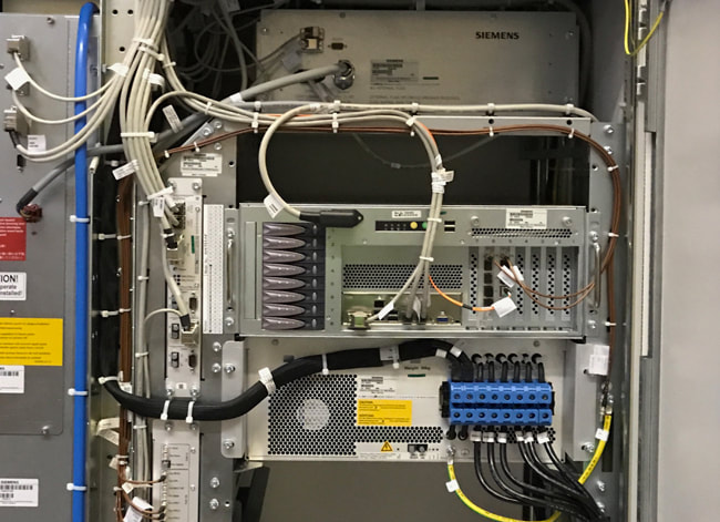
Left: x-, y-, and z-gradient amplifiers. The black vertically-oriented hoses contain coolant that is circulated to remove the considerable heat generated by these amplifiers. Above right: The array processor, where numerical processing of the MR data, including Fourier transformation, takes place. |
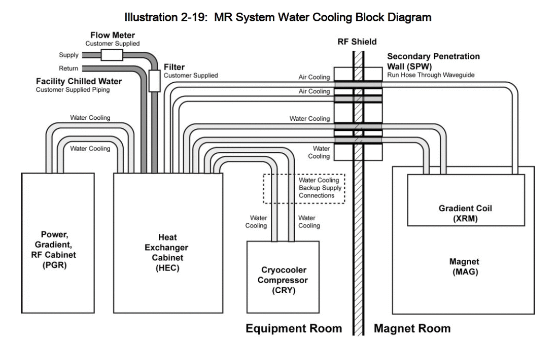
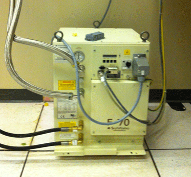
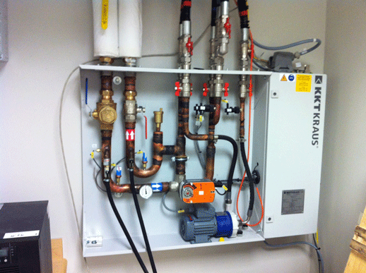
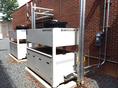
Components of the cooling system for the magnet, amplifiers, and gradient coils are pictured above. These include a cryocooler compressor or "helium pump" (that circulates liquid helium around the magnet) and a heat exchanger or "chiller" (that pumps an antifreeze-water mixture to cool the gradients as well as taking some heat away from the helium system).
The wires and tubing from the electrical and cooling equipment passes through penetration panels on common wall between the magnet room and equipment room.
The wires and tubing from the electrical and cooling equipment passes through penetration panels on common wall between the magnet room and equipment room.

Control Room. This is immediately outside the magnet room. It contains the operator console, keyboard, communication devices, EKG and oxygen monitors and computer equipment that controls the scanner (box on floor at lower right of desk).
Advanced Discussion (show/hide)»
No supplementary material yet. Check back soon.
References
Department of Veterans Affairs MRI Design Guide, 2008. An official document to assist VA Hospitals in designing the layout for clinical MRI systems. Contains many useful recommendations applicable to all sites.
Department of Veterans Affairs Design Drawings and Specifications. Second part of the above document containing detailed specifications and engineering drawings.
Magnetom Skyra Planning Guide. Siemens Medical Systems, 2013. A list of siting requirements and specifications for their 3.0T scanner.
Related Questions
What are the ACR Safety Zones?
What are the ACR Safety Zones?


