|
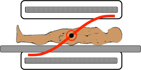
Ideally an imaging gradient should produce an incremental magnetic field whose intensity varies linearly with distance from magnet isocenter. In other words, if the gradient field at distance D equals S, the gradient contribution at distance 2D should equal 2S. Like magnetic field homogeneity, gradient linearity falls off significantly the farther one gets from isocenter.
|
No uniformly agreed upon definition for gradient linearity is used by all manufacturers. One of the oldest and most popular methods is called the differential linearity error, which gives a maximum percent gradient error over a given spherical volume. For example, a gradient might be described to have a linearity error of less than 2% within 50 cm of isocenter. This method mirrors the definition of magnetic field homogeneity as % field change over a defined spherical volume (DSV).
|
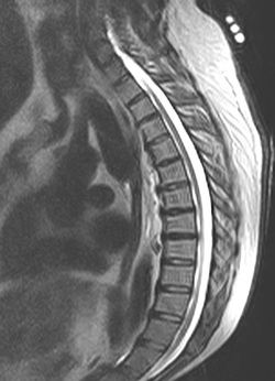
Gradient linearity issues are often subtle and create minor spatial distortion artifacts and blurring at the extreme margins of MR images. Even when severe (see example right), such artifacts can still be generally "read around" and cause no problem for routine image interpretation. However, even small linearity distortions may be critical for when MR is used for interventional purposes, such as precise placement of deep brain stimulators or biopsies, where submillimeter spatial accuracy is required.
A number of image processing techniques exist to correct for gradient induced spatial distortions and are commonly employed by all manufacturers (e.g., GE Healthcare's "Gradwarp"). Such methods include use of precomputed displacement tables, phase mapping, and/or the use of "forward" and "reverse" frequency-encoding gradients.
|
Advanced Discussion (show/hide)»
No supplementary material yet. Check back soon!
References
Doran SJ, Charles-Edwards L, Reinsberg SA, Leach MO. A complete distortion correction for MR images: I. Gradient warp correction. Phys Med Biol 2005; 50:1343–1361.
Doty FD. MRI gradient coil optimization. In: Blumler P, Blumich B, Botto R, Fukushima E (eds), Spatially Resolved Magnetic Resonance. Wiley; 1998, pp 647-674.
Glover GH, Pelc NJ. Method for correcting image distortion due to gradient nonuniformity. US Patent # 4,591,789, May 27, 1986. (Original GE patent that forms the basis of their "Gradwarp" nonlinearity correction technique).
Hidalgo-Tabon SS. Theory of gradient coil design methods for magnetic resonance imaging. Concepts Mag Res Part A 2001; 36A:223-242.
Related Questions
How do you make a z-direction gradient?
How do you make x- and y-direction gradients?
What are gradient coils?
How do you make a z-direction gradient?
How do you make x- and y-direction gradients?
What are gradient coils?


