|
To stimulate the NMR spin system, an RF-coil must produce a time-varying excitation field B1(t) with the following characteristics:
✔ B1(t) must have components that rotate near the resonant frequency (ωo), and ✔ B1(t) must have components perpendicular to the static magnetic field (Bo) |
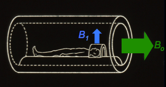
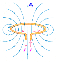
The simplest form of such an RF-transmit coil is a single loop oriented at right angles to the main magnetic field (see figure right). By driving a sinusoidal alternating current through this loop at the Larmor frequency, an oscillating magnetic field perpendicular to Bo is produced. Somewhat more sophisticated variations of this coil can be easily imagined, such as 2-loop (Helmholz) or multi-loop (solenoid) configurations.
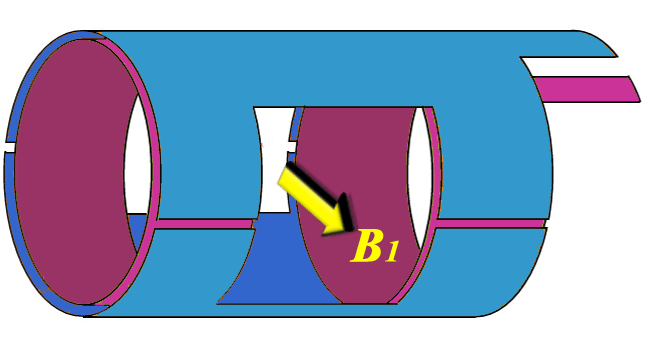
Because they generate an oscillating B1 field in only a single dimension, single-loop, Helmholz, and solenoid RF-coils are called linearly polarized (LP). Although not immediately obvious, this configuration is highly inefficient for MRI in that half of the transmitted power is wasted.
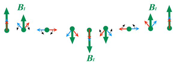
Some insight into the nature and inefficiency of linear polarization can be appreciated by considering the diagram below. Here you can see that a field like B1 (depicted as a big green arrow) oscillating at the resonance frequency (ωo) can be decomposed into two counterrotating subfields (red and blue arrows), each half as large. One of these subfields (red arrow) rotates in the same direction and frequency (ωo) as the spins undergoing NMR; the other subfield (blue arrow) rotates in the opposite direction and frequency (−ωo). Only the subfield associated with red arrow is effective at inducing net nuclear transitions and a change in net nuclear magnetization required for MRI. The other subfield is ineffective for NMR and serves only to deposit unwanted thermal energy into tissue.
Some insight into the nature and inefficiency of linear polarization can be appreciated by considering the diagram below. Here you can see that a field like B1 (depicted as a big green arrow) oscillating at the resonance frequency (ωo) can be decomposed into two counterrotating subfields (red and blue arrows), each half as large. One of these subfields (red arrow) rotates in the same direction and frequency (ωo) as the spins undergoing NMR; the other subfield (blue arrow) rotates in the opposite direction and frequency (−ωo). Only the subfield associated with red arrow is effective at inducing net nuclear transitions and a change in net nuclear magnetization required for MRI. The other subfield is ineffective for NMR and serves only to deposit unwanted thermal energy into tissue.
|
In the 1980's linearly polarized transmit-receive RF-coils were the norm, but by the 1990's had become largely replaced by quadrature or circularly polarized (CP) coils. The physical principles underlying circular polarization will be addressed in the next several Q&A's. |
|
Today linearly polarized transmit RF-coils are largely restricted for use in very small animal imaging and spectroscopy applications (such as double resonance cross-polarization or high-power ¹H-decoupling).
|
Although now seldom employed for RF-transmission, linearly polarized coils are nevertheless widely used as receive-only RF coils in modern MR scanners. Here they are frequently assembled into vast arrays for parallel imaging. Several upcoming Q&A's will address how these coils are arranged and interact for reception of the MR signal.
Advanced Discussion (show/hide)»
Transmit-receive LP coils are not completely dead for human clinical MR imaging! Some specially designed solenoid coils have been developed for interventional procedures, such as 3D breast biopsy. See, for example, Smith MR, Zhai X, Kurpad KN et al. Excite and receive solenoid radiofrequency coil for MRI-guided breast interventions. Magn Reson Med 2011; 65:1799-1804.
References
Glover GH, Hayes CE, Pelc NJ, et al. Comparison of linear and circular polarization for magnetic resonance imaging. J Magn Reson 1985; 64:255-270.
Doty FD, Enzmenger G, Kulkarni J, et al. Radiofrequency coil technology for small animal MRI. NMR Biomed 2007; 20: 304–325
Glover GH, Hayes CE, Pelc NJ, et al. Comparison of linear and circular polarization for magnetic resonance imaging. J Magn Reson 1985; 64:255-270.
Doty FD, Enzmenger G, Kulkarni J, et al. Radiofrequency coil technology for small animal MRI. NMR Biomed 2007; 20: 304–325
Related Questions
What are the function(s) of radiofrequency (RF) coils?
What is the difference between linearly polarized (LP) and a circularly polarized (CP) coils?
What are the function(s) of radiofrequency (RF) coils?
What is the difference between linearly polarized (LP) and a circularly polarized (CP) coils?


