Field-of-view (FOV) refers the distance (in cm or mm) over which an MR image is acquired or displayed. The FOV is typically divided into several hundred picture elements (pixels), each approximately 1 mm² in size. Although the field-of-view and pixel size may vary in each of the cardinal directions, for clarity of explanation we will consider only the symmetric, 2-dimensional case where FOVx = FOVy = FOV and Δx = Δy = Δw.
The defined field-of view (FOV) and pixel width (Δw) determine the number of digitized samples in k-space that must be obtained to reconstruct an image with the desired resolution. As shown in the diagrams below, FOV is inversely proportional to the spacing between samples in k-space. Specifically, Δk = 1/FOV.
From symmetry considerations an inverse relation also holds between pixel width (Δw) and the range between the highest positive (+kmax) and negative (−kmax) spatial frequencies in k-space. Defining kFOV = (+kmax) − (−kmax) = 2 kmax, the relationship is given by Δw = 1/kFOV.
From symmetry considerations an inverse relation also holds between pixel width (Δw) and the range between the highest positive (+kmax) and negative (−kmax) spatial frequencies in k-space. Defining kFOV = (+kmax) − (−kmax) = 2 kmax, the relationship is given by Δw = 1/kFOV.
For most people it is not immediately obvious why either Δk = 1/FOV or Δw = 1/kFOV. So, join the confusion! Hopefully the discussion below will allow you to feel a little more comfortable with these important results. We first consider why Δk = 1/FOV.
|
Recall from a prior Q&A that Fourier analysis allows a simple signal to be decomposed into a sum of sine waves with integral harmonic frequencies (ω, 2ω, 3ω, etc.)
The Fourier projection of spatial frequencies in k-space from an imaged object follows a similar pattern, where complex exponentials (cos nωt + i sin nωt) replace simple sine waves but continue to have integer numbers of oscillations across the FOV. Each pair of successively sampled lines of k-space differ by exactly 1 cycle over the field of view. For example, the spatial frequency difference (Δk = kn+1 − kn) for lines kn+1 and kn is given by
|
Δk = (n+1)/FOV − n/FOV = 1/FOV
Like the expression Δk = 1/FOV, the equation Δw = 1/kFOV is not intuitively obvious. In this case we need to think about how many phase cycles in k-space are needed to appropriately characterize the smallest desired dimension (Δw) of the image.
As shown below, the answer is that one full phase cycle is needed to uniquely differentiate each pixel. If there are N pixels of width (Δw) spanning the field-of-view (FOV), then N phase cycles are needed. We have previously defined kFOV = 2kmax to correspond to this required spatial frequency. Since spatial frequency (k) is [# cycles/distance], we can write kFOV = N /FOV. But pixel width (Δw) equals FOV / N. It therefore follows directly that kFOV = 1 /Δw.
The reason these paired equations are important is that they tell us explicitly how the spacing or location of samples in k-space affects FOV and pixel width.
|
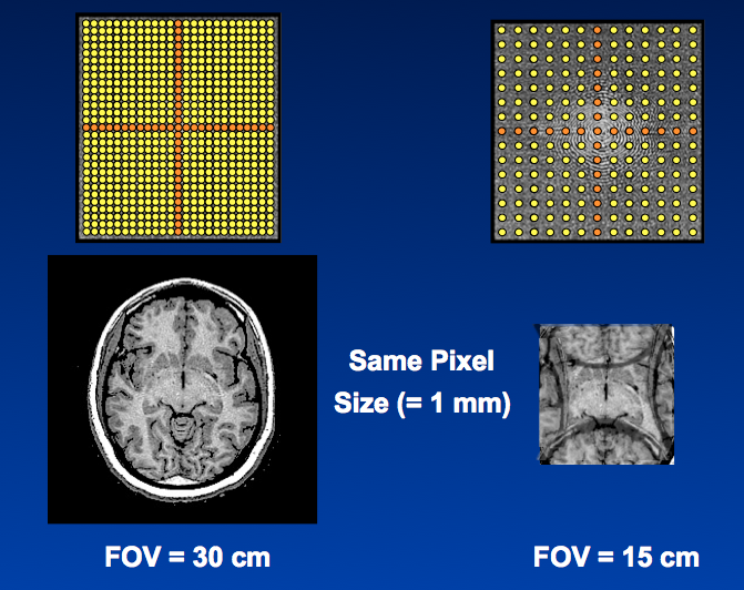
The first example demonstrates the inverse relationship between data spacing and image FOV. On the left, the k-space data sampling rate has produced an image with a 30 cm FOV. On the right, the the spacing between data points (Δk) has doubled. The result is an image with the same pixel size but a FOV half as large (15 cm). The edges of the brain outside this smaller FOV have now been "wrapped" over the sides of the reconstructed image, a phenomenon known as aliasing.
|
|
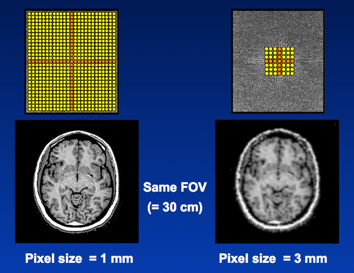
In the second example we have kept the data sampling rate and spacing (Δk) the same. However, this time we have sampled only the middle third of k-space, reducing kFOV by a factor of ⅓. With this k-space manipulation, the FOV remains unchanged, but the pixel width (Δw) has been tripled from 1 mm to 3 mm. The larger pixel size means in-plane spatial resolution has decreased, an expected result because only the central (lower spatial frequency) portions of k-space have been sampled.
|
If you are still confused, don't worry. After all, this is the Q&A Tab labeled "K-space (advanced)." For those more mathematically inclined the following YouTube video by Eric Wong may offer some further insight.
Advanced Discussion (show/hide)»
No supplementary material yet. Check back soon!
References
Mezrich R. A perspective on k-space. Radiology 1995; 195: 297-315. [review].
Miller K. MRI image formation (ppt). On-line lecture notes available atusers.fmrib.ox.ac.uk/~karla/teaching/image_formation.ppt
Mezrich R. A perspective on k-space. Radiology 1995; 195: 297-315. [review].
Miller K. MRI image formation (ppt). On-line lecture notes available atusers.fmrib.ox.ac.uk/~karla/teaching/image_formation.ppt


