|
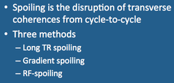
Spoiling refers to the disruption of transverse coherences that may persist from cycle to cycle in a GRE sequence. Spoiling ensures that immediately before each RF-pulse, the steady-state magnetization has no transverse components. The longitudinal magnetization (Mz) does reach a steady-state (Mss) in the z-direction, but the transverse magnetization (Mxy) is obliterated at the end of each cycle and no transverse steady-state (M'ss) is established.
|
Believe it or not, it is actually quite difficult to achieve perfect spoiling, as pesky stimulated echoes and distant coherences have a habit of reappearing! Three methods may be used alone or in combination to spoil transverse magnetization:
1. Long TR spoiling. When TR>>T2*, the transverse magnetization will naturally decay to zero by the end of the cycle. Thus any gradient echo sequence using TR values of several hundred milliseconds or longer will be "naturally" spoiled. Spoiling can be enhanced by operating the sequence in a 2D multi-slice mode. Here, off-resonant effects from RF-pulses for other slices and their associated imaging gradients will further disrupt transverse coherences. Sequences that take advantage of this method include GE's MPGR and MERGE, Siemens' MEDIC, and Philips' multi-FFE.
1. Long TR spoiling. When TR>>T2*, the transverse magnetization will naturally decay to zero by the end of the cycle. Thus any gradient echo sequence using TR values of several hundred milliseconds or longer will be "naturally" spoiled. Spoiling can be enhanced by operating the sequence in a 2D multi-slice mode. Here, off-resonant effects from RF-pulses for other slices and their associated imaging gradients will further disrupt transverse coherences. Sequences that take advantage of this method include GE's MPGR and MERGE, Siemens' MEDIC, and Philips' multi-FFE.
2. Gradient spoiling. In this method spoiling is performed by applying the slice-select (and sometimes readout) gradients with variable amplitudes at the end of each cycle just before the next RF pulse. The strength of the spoiler gradient is varied linearly or semi-randomly from view to view. This method is not entirely adequate by itself, as the spoiling will be spatially nonuniform because gradients produce spatially varying fields. This leads to the third and best method....
3. RF-spoiling. Here the phase of the RF-carrier is changed according to a predefined formula from view to view. Using a completely randomized pattern of phase changes is not ideal in that unintended spin clustering may occur and the degree of spoiling may change from one interval to the next. A superior method is to increment the phase quadratically using a recursive formula. In both theory and practice, RF-spoiling is superior to gradient spoiling because it does not generate eddy currents and is spatially invariant. RF-spoiling is universally used by all vendors for their dedicated spoiled sequences. These include GE's SPGR and FSPGR, Siemens' FLASH and VIBE, and Philips' T1-FFE.
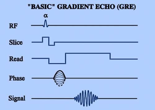
Simplified pulse timing diagrams for a "Basic" (unspoiled) GRE sequence and and one using both gradient and RF-spoiling are shown below. The diagrams have been simplified for clarity (e.g. rewinder gradients and other subtleties have been left out).
Simplified pulse timing diagrams for a "Basic" (unspoiled) GRE sequence and and one using both gradient and RF-spoiling are shown below. The diagrams have been simplified for clarity (e.g. rewinder gradients and other subtleties have been left out).
Advanced Discussion (show/hide)»
Many vendors have adopted an RF phase-cycling pattern based on the work of Zur et al (1991). Here the phase at step j is denoted by Φj and given by the recursive formula
Φj = ½ Φo (j2 + j + 2)
where Φo is the initial RF phase. This formula leads to the following series of phase angles: Φo, 2Φo, 4Φo, 7Φo, 11Φo, etc. The starting phase angle (Φo) is often selected to be either 117º or 123º. The reason for choosing such an apparently bizarre value for Φo is because no small integer multiple of either 117º or 123º is evenly divisible by 360º.
References
Denolin V, Azizieh C, Metens T. New insights into the mechanisms of signal formation in RF-spoiled gradient echo sequences. Mag Reson Med 2005; 54:937-954.
Epstein FH, Mugler JP III, Brookeman JR. Spoiling of transverse magnetization in gradient-echo (GRE) imaging during the approach to steady state. Magn Reson Med 1996;35:237-245.
Elster AD. Gradient echo imaging: techniques and acronyms. Radiology 1993; 186:1-8.
Haase A, Frahm J, Matthaei KD. FLASH imaging: rapid NMR imaging using low flip angle pulses. J Magn Reson 1986: 67: 258-266.
Zur Y, Wood ML, Neuringer LJ. Spoiling of transverse magnetization in steady state sequences. Magn Reson Med 1991; 21:251-263.
Related Questions
Why would you want to use a spoiled-GRE technique? How do you pick the parameters?
Why would you want to use a spoiled-GRE technique? How do you pick the parameters?


