|
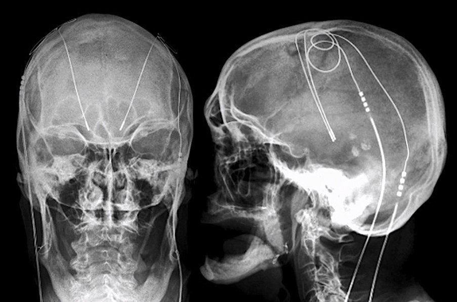
Deep brain stimulation (DBS) systems are approved for the treatment of Parkinson's disease, essential tremor, dystonias, depression, and obsessive-compulsive disorder. An implanted pulse generator (IPG) is typically placed subcutaneously in the infraclavicular fossa, connected by wires that travel up the neck and enter the skull through small burr holes. Electrodes at the distal end of each wire terminate in the thalamus, internal globus pallidus, or subthalamic nucleus.
|
|
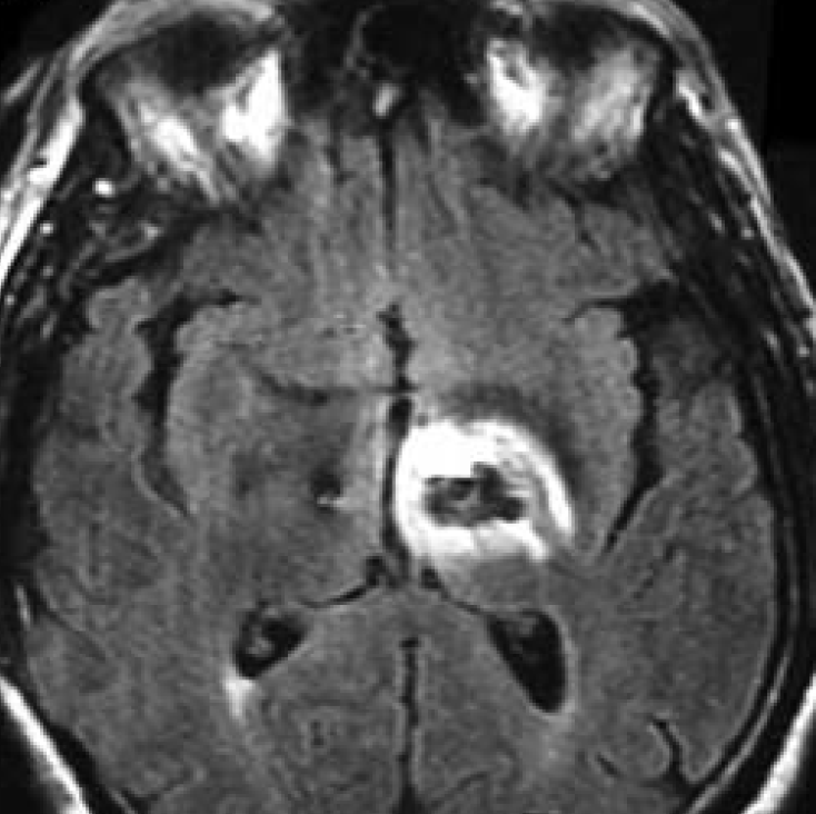
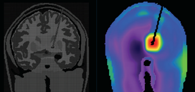
The primary MR safety concern for DBS systems is heating at the electrode tip due to induced currents and the antenna effect. Antennas capture electromagnetic waves and develop standing-wave patterns of voltage and current that are concentrated near their tips. Three clinical cases have been reported in association with MRI, including one leaving permanent neurologic deficits (see image left)
|
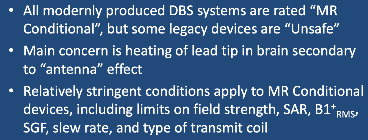
Three companies produce all DBS systems worldwide: Abbott (St. Jude), Boston Scientific, and Medtronic. All new DBS systems currently sold are MR Conditional (with some very stringent requirements outlined below). Several MR Unsafe legacy devices may still be encountered, including the St. Jude Libra®, LibraXP®, and Brio® models; the Boston Scientific Vercise® (Model DB-1110-C), and the Medtronic Reclaim® (Model 3391). Some even older models (before 2010) may not be technically rated as MR Unsafe, but may behave unpredictably due to the presence of magnetic reed switches causing IPG malfunction in the magnetic field.
What are the Conditions?
The precise conditions that must be followed for safe MR Scanning of DBS systems vary somewhat among the models and manufacturers, but share many common features:
- Device identification. The exact model/serial numbers from the various components of the DBS system, including the IPG, leads, and lead caps or extensions (if present) must be established with certainty. This can be done by reviewing operative notes from the medical record or the patient's information card. For some systems this information can be obtained by wireless interrogation of the IPG.
- Determine location of components. Verify (by x-ray if necessary) that the IPG has been implanted subcutaneously in the upper chest and that the wires ascend in the neck along the same side as the IPG (Intracranially, the leads may cross the midline). Commonly the leads are longer than anatomically necessary and the surgeon coils the excess leads subcutaneously in the scalp or subcutaneously near the IPG. As a rule, less induction current will be generated by multiple small loops than a single large loop.
- Special considerations for "lead only" systems. MR scanning of DBS systems without an IPG in place is permissible (the so-called "Lead Only" Configuration) with some additional imaging parameter restrictions. Proximal bare leads should be capped with "lead boots" and no extensions are allowed. A burr hold cover/plate may be required.
- Pre-MRI evaluation/interrogation of the DBS system. The IPG battery should be fully charged and lead impedances should measure within expected values. The IPG should be turned off or placed in "MRI Mode" if available.
- MRI Equipment and Protocols. These conditions will vary significantly between manufacturers and DBS models. All current MR-conditional DBS devices are restricted to ¹H imaging in horizontal bore cylindrical magnets operating at 1.5 or 3.0T. Only the supine or prone patient positions are allowed. Limits for maximum spatial gradient, gradient slew rate, total imaging time, and RF power dissipation measured by average SAR or maximum B1+RMS must be followed explicitly. For several models there are restrictions on the use of various transmit coils and power deposition limits depending on the location of magnet isocenter. More limitations will exist when the body coil is used for RF-transmission rather than localized transmit-receive head or knee coils.
- Before, During, and After MRI. The patient must be in a cognitive state able to provide immediate feedback concerning any problems during the examination. Visual and auditory monitoring should be continuously performed during the scan, and the patient verified as normal and responsive between sequences. After the exam, MRI-mode should be turned off and settings returned to pre-MRI values.
Advanced Discussion (show/hide)»
A common situation that arises concerns patients with partially implanted leads (i.e., those without an IPG attached). These patients should be considered eligible for a head only study using a transmit-receive head coil. The percutaneous leads should be wrapped with thermally and electrically insulating material and kept out of contact with the patient. The leads should also be kept straight (no loops) and running down center of head coil. Even still, one patient has been injured using this method (see article by Spiegel et al in references below.)
References
Bhusal B, Nguyen BT, Sanpitak PP, et al. Effect of device configuration and patient’s body composition on the RF heating and nonsusceptibility artifact of deep brain stimulation implants during MRI at 1.5T and 3T. J Magn Reson Imaging 2021; 53:599-610. [DOI LINK]
Boutet A, Chow CT, Narang K, et al. Improving safety of MRI in patients with deep brain stimulation devices. Radiology 2020; 296:250-262. [DOI LINK]
Boston Scientific. ImageReady™ MRI guidelines for Boston Scientific deep brain stimulation systems. 2019: 1-33. (downloaded May 2021, please check manufacturer's site for most up-to-date version.)
Golestanirad L, Kirsch J, Bonmassar G, et al. RF-induced heating in tissue near bilateral DBS implants during MRI at 1.5 T and 3T: The role of surgical lead management. NeuroImage 2019; 184:566-576. [DOI LINK]
Henderson JM, Tkach J, Phillips M, et al. Permanent neurological deficit related to magnetic resonance imaging in a patient with implanted deep brain stimulation electrodes for Parkinson's disease: case report. Neurosurgery 2005; 57:E1063 (Report of hemorrhage and edema with permanent injury surrounding DBS electrodes following MRI of the lumbar spine. This case was unusual in that the DBS wires and pulse generator were placed in the abdomen and whole-body RF-excitation was used).
Iacono MI, Makris N, Mainardi L, et al. MRI-based multi scale model for electromagnetic analysis in the human head with implanted DBS. Comput Math Methods Med 2013; 2013:694171. [DOI Link] Kazemivalipour E, Bhusal B, Vu J, et al. Vertical open-bore MRI scanners generate significantly less radiofrequency heating around implanted leads: A study of deep brain stimulation implants in 1.2T OASIS scanners versus 1.5T horizontal systems. Magn Reson Med 2021; 86:1560-1572. [DOI LINK] (Although not approved for 1.2T vertical bore scanners, DBS leads may undergo significantly less heating with this MR configuration, allowing more energy-intensive pulse sequences to be used).
Konings MK, Bartels LW, Smits HFM, Bakker CJG. Heating around intravascular guidewires by resonating RF waves. J Magn Reson Imaging 2000; 12:79-85. (mathematical theory of the antenna effect).
Spiegel J, Fuss G, Backens M, et al. Transient dystonia following magnetic resonance imaging in a patient with deep brain stimulation electrodes for the treatment of Parkinson disease. J Neurosurg 2003; 99:772-774. (First reported case of an adverse effect in a DBS patient undergoing MRI. Patient had bilateral electrodes placed externally but no implanted neurostimulator. The field strength was 1.0T but other imaging parameters seemed reasonable — transmit-receive head coil, SAR and slew rate within recommended limits, proper handling of external wires. Nevertheless the patient developed dystonic/ballistic leg movements immediately after MRI requiring several months to resolve. This may have resulted from a so-called "antenna effect" due to currents induced in the long leads.)
Tronnier VM, Staubert A, Hähnel S, Sarem-Alsani A. Magnetic resonance imaging with implanted neurostimulators: An in vitro and in vivo study. Neurosurgery 1999; 44:118-126.
Zrinzo L, Yoshida F, Hariz MI, et al. Clinical safety of brain magnetic resonance imaging with implanted deep brain stimulation hardware: large case series and review of the literature. World Neurosurg 2011; 76:164-172. (review of complications up to 2011 including a new case of peri-electrode edema and transient neurological symptoms after MRI using recommended parameters).
Related Questions
Can patients with spinal cord stimulators undergo MRI?
What MRI limitations are there for scanning epilepsy patients with depth electrodes and grids?
Can patients with spinal cord stimulators undergo MRI?
What MRI limitations are there for scanning epilepsy patients with depth electrodes and grids?


