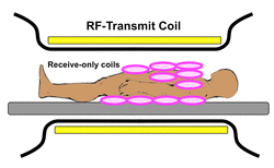
The RF-coils (birdcage, TEM, etc) described in the immediately preceding questions were primarily designed to transmit the B1 field, but with additional circuitry could also be used in T/R mode to receive the MR signal. In most modern MR scanners, however, RF transmission and reception functions have been largely separated and delegated to two different types of coils. In the typical arrangement, RF-transmission is performed by a body RF-coil (of the birdcage or TEM variety) located just beneath the inner wall of the scanner bore. RF-reception is delegated to one or more surface coils placed close to the patient's body as illustrated in the diagram above.
|
The simplest form of receive-only surface coil is the single loop design. Changes in magnetic flux (generated by the precession of net nuclear magnetization within the subject after RF-stimulation) induces a small current within the coil in accordance with Faraday's Law. The tiny received MR signal (measured in microvolts) is then amplified, digitized, and processed to extract frequency, phase and amplitude information allowing construction of the MR image.
|
|
|
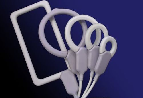
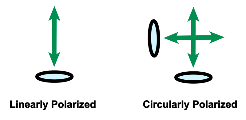
As shown in the diagram above, a wide range of loop coil configurations exist. Most of the simpler single coils and those arrayed in a plane are linearly polarized. This means that they receive the components of the MR signal in a single direction only. More complexly designed planar coils and even simple loop coils in 3D arrays are circularly polarized and capable of quadrature detection. Quadrature detection offers an improvement in signal-to-noise by a factor of √2 (≈ 1.41) compared to that of linearly polarized coils.
Regardless of coil type (LP or CP), both the coil size and its distance from the object imaged are critical determinants of coil sensitivity (and hence signal-to-noise ratio). The penetration depth for reception from a simple loop RF surface coil is typically only about 50-75% of the coil's diameter. Based on this underlying physics, the current trend for MR signal detection is to use large arrays of small loop coils located on or close to the patient. |
Advanced Discussion (show/hide)»
No supplementary material yet. Check back soon!
References
GE Healthcare. MR Field Notes: RF Coils...They've come a long, long way. 2005.
Gruber B, Froeling M, Leiner T, Klomp DWJ. RF coils: a practical guide for nonphysicists. J Magn Reson Imaging 2018:48:590-604. (Comprehensive modern review)
Hayes CE, Axel L. Noise performance of surface coils for magnetic resonance imaging at 1.5T. Med Phys 1985; 12:604-7.
Kumar A, Bottomley PA. Optimized quadrature surface coil designs. Magn Reson Mater Phy 2008; 21:41-52.
Related Questions
I don't understand all the different types of coils in MR. Can you make sense of these?
What are the function(s) of radiofrequency (RF) coils?
What is the difference between phased and parallel coil arrays?
I don't understand all the different types of coils in MR. Can you make sense of these?
What are the function(s) of radiofrequency (RF) coils?
What is the difference between phased and parallel coil arrays?


