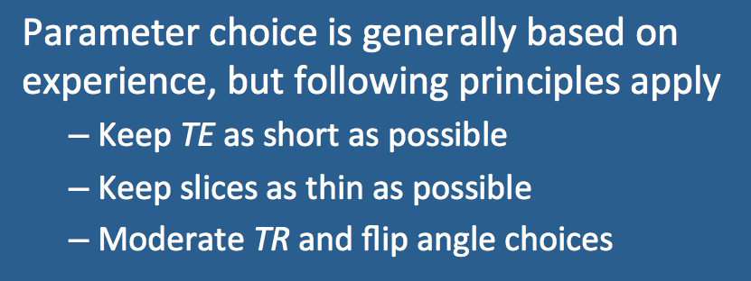
Certain trade-offs exist in the selection of parameters for a time-of-flight MRA sequence. Although the final parameters will likely be determined empirically, the reader should be aware of the following compromises when selecting TR, TE, and flip angle (α).
|
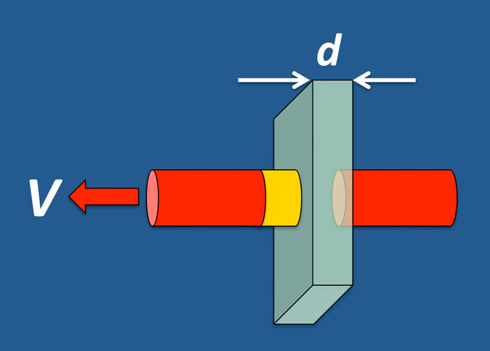
Relationship between TR, slice thickness (d), and flow velocity (V). Maximum flow-related enhancement occurs when inflowing blood completely replaces that present in a given slice. When flow is perpendicular to the slice, maximum enhancement occurs when
V ≥ d / TR
For example, with V = 50 cm/sec and TR = 40 ms (0.04 sec), blood is completely replaced as long as the slice thickness (d) ≤ 2.0 cm.
|
Accordingly, flow-related (TOF) enhancement is maximized for perpendicular flow, thin slices, long TR, and high velocities.
Effect of TR. Increasing TR allows more time for T1 relaxation processes to occur between pulses. Although greater inflow enhancement may be possible, increasing TR is often undesirable because the signal from background tissue also increases, with loss of vessel conspicuity. Moreover, increasing TR also lengthens scan time. Typical TR values are generally in the range of 15-35 ms for both 2D and 3D TOF MRA at high field.
Effect of flip angle (α). Increasing flip angle decreases signal from static tissue due to greater saturation and increases relative signal from blood at the entry slice. For rapidly flowing vessels, increasing flip angle will lead to more background suppression with improved conspicuity of vessels. For slowly flowing vessels, however, the flip angle may need to be reduced. Depending on the application, flip angles from 30º to 70º are commonly employed for 2D TOF and 10° to 30° for 3D TOF.
Effect of TE. Increasing TE will increase the signal from vessels, but this theoretical benefit is offset by signal loss due to spin-phase dispersion at long TE values. Generally, TE is selected to be the minimum allowable for a given pulse sequence. On modern scanners, this usually translates to TE's on the order of 3-7 ms. Gradient-moment nulling can be used to overcome some of these spin-phase losses, but this will increase the minimum TE slightly. Within these limits, selecting a value of TE close to a fat-water out-of-phase value (e.g. 2.2, 4.4 or 6.6 msec at 1.5T) may be useful for improving background suppression.
Advanced Discussion (show/hide)»
What about TOF venography?
Yes, as you guessed a different parameter strategy must be used, somewhat the opposite to those principles for optimizing visualization of arteries. First, the location of the saturation bands must be switched to spoil the signal from arteries, and these bands must be made larger than the venous bands since arterial flows are greater. To increase sensitivity to slow flow, both the TR and flip angle should be reduced, but the TE should be lengthened.
References
Saloner D. An introduction to MR angiography. Radiographics 1995;15:453-465. (Older review; good discussion of TOF and PC MRA)
Stuelke S. MRprotocols.com. A database of MRI and MRA protocols.
Saloner D. An introduction to MR angiography. Radiographics 1995;15:453-465. (Older review; good discussion of TOF and PC MRA)
Stuelke S. MRprotocols.com. A database of MRI and MRA protocols.
Related Questions
How does varying the flip angle improve TOF MR angiography?
How does varying the flip angle improve TOF MR angiography?

