|
Array coil systems are collections of small surface coils whose signals may be combined but generally feed into independent receiver circuitry.
Small-diameter surface coils near the patient have high sensitivity but limited anatomical coverage. By combining multiple small coils into large arrays it is possible to obtain the best of both worlds — high signal-to-noise and large fields of view. |
The design and configuration of array coils has evolved over the last 25 years.
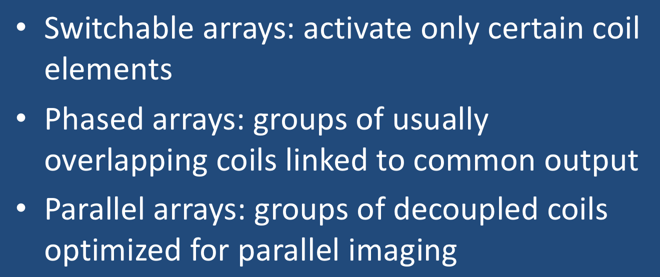
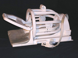
Switchable arrays. The need for coil arrays was first recognized in spine imaging. In the 1980's only single-segment coils (i.e., lumbar, thoracic, or cervical) were available that had to be moved or changed for each spinal area imaged. By 1990 switchable or ladder spine arrays came into use. These were simply three single-segment spine coils embedded into one long padded "CTL-coil" on which the patient would lie. Because early MR scanners generally had only a single quadrature receiver channel, only a single spinal segment could be imaged at any one time. However, the segments could be electronically switched without moving the patient so this was viewed as a significant achievement for the time!
Even in modern surface coil design, some switchable features remain. For example, because of limited numbers of receiver processing channels, a technologist may still be required to select only specific coil segments to activate when imaging the entire spine.
|
Phased arrays. This next major technical advance used smaller coils that could be combined or fed into separate receiver chains. The term "phased array" derives from antenna theory where large groups of small antennas (such as in radar installations) are coupled together and used to enhance overall signal or transmission properties.
As originally described MR phased-arrays employed coil overlapping (to minimize coupling between nearest-neighbor coils) and low input impedance preamplifiers (to isolate the relatively weak coupling between non-nearest neighbors). |
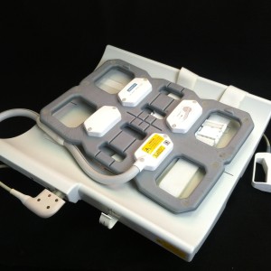
N independent phased array coils, each with their own amplifiers and receiver channels, will ideally increase signal-to-noise by a factor of √N. So for the 4-coil phased array pictured below, the signal-to-noise ratio should be 2X higher than that for a single coil. In practice such large gains are not usually achieved, but they can be substantial nevertheless.
|
Parallel Arrays. The last decade has seen the widespread application of parallel imaging methods in nearly all aspects of MRI. In parallel imaging, differential weighting of signals from multiple small surface coils are used to determine the spatial origin of the signal, thus reducing the need for time-consuming gradient-encoding steps.
To make the complex sensitivities of these coils sufficiently distinct for spatial encoding, the individual coil elements should be free of magnetic interactions. This means that the large overlap between coils (as seen in most phased-array configurations) is generally avoided for parallel imaging and coil decoupling circuitry is essential. Thus while all parallel imaging coils are "phased arrays", not all phased array coils are suitable for parallel imaging. The number of available coil segments is generally much greater the number of receiver channels. This is because coil elements are cheap to produce, whereas receiver channel technology is expensive, requiring a complete chain of amplifiers, digitizing circuitry, and computational engine to process the individual signals collected. |
The nomenclature gets a little confusing, but the hierarchy to be remembered is:
Coil Elements > Segments > Channels
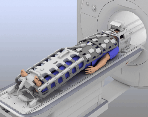
For example, consider a total spine parallel imaging array constructed of 32 individual elements — small linearly polarized simple loop receiver coils distributed from the cervical to lumbar regions. These 32 coils might be paired to form 16 quadrature coil segments (4 cervical, 8 thoracic, and 4 lumbar) that in turn could be connected into up to 8 independent receiver channels.
Segments have two fundamental design characteristics: 1) They are composed of one or more basic coil elements; and 2) They are equipped with both "decoupling" and "tune and match" circuitry allowing them to be connected to a single receiver channel.
Channels are independent, complete electronic chains required for processing information received from a coil segment. Channels include amplifiers, filters, analog-to-digital conversion circuitry, demodulation/mixer devices, and image processing capability. The output of each channel is generally a partial view of the entire anatomy being imaged, subsequently combined with output from the other channels to produce the final MR image.
In the spine array example above there are 16 available segments but only 8 independent receiver channels. Hence it would be possible with this configuration to image only half the spine in one acquisition by electronically selecting which 8 segments to use. The 8 unused coils would have their decoupling circuitry activated, making them appear invisible to the system.
Alternatively, if only a single spine region (such as the cervical region) was to be imaged, only the 4 cervical coil segments would be activated. The 12 unused lower coil segments would be detuned and 4 unused receiver channels would be turned off.
Advanced Discussion (show/hide)»
The process by which the MR signal gets detected and converted into useful data is rather involved. If you are interested, clicking on the button below will take you to a secret/hidden Q&A page where much is revealed!
References
Fujita H. New horizons in MR technology: RF coil designs and trends. Magn Reson Med Sci 2007;6:29-42.
Gruber B, Froeling M, Leiner T, Klomp DWJ. RF coils: a practical guide for nonphysicists. J Magn Reson Imaging 2018:48:590-604. (Comprehensive modern review)
Kaufman L, Arakawa M, McCarten BM, et al. Switchable MRI RF coil array with individual coils having different and overlapping fields of view. US Patent #4,881,034, November 14, 1989.
Ohliger MA, Sodickson DK. An introduction to coil array design for parallel MRI. NMR Biomed 2006;19:300-315.
Roemer B, Edelstein WA. Nuclear magnetic resonance (NMR) imaging with multiple surface coils. US Patent #4,825,162, April 25, 1989.
Roemer PB, Edelstein WA, Hayes CE, et al. The NMR phased array. Magn Reson Med 1990; 16: 192-225.
Related Questions
How do receive-only coils work?
How is the MR signal converted to useful data for image processing?
How do receive-only coils work?
How is the MR signal converted to useful data for image processing?
|
© 2024 AD Elster, ELSTER LLC
All rights reserved. |
|


