|
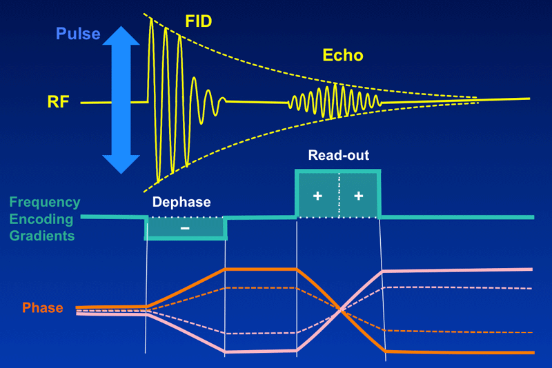
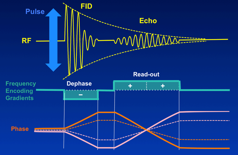
To the right is a pulse timing diagram of a very simple gradient echo sequence, where a GRE is generated by applying a frequency-encoding gradient using two lobes of opposite polarity. The (first) dephase lobe causes spins to fall out of phase as a function of their position within the gradient. The (second) readout lobe brings these spins back into phase to create the echo.
|
By convention, the height of each gradient lobe on this diagram is proportional to the strength of the gradient; its width reflects how long the gradient is applied. When a gradient is turned on spins at different locations will temporarily precess at different frequencies based on their position along the gradient. The area under a lobe (gradient strength x time) is proportional to the phase shift experienced by a given spin. (If you don't remember why this is so, you may need to review some basic concepts about phase and frequency from a prior Q&A).
|
The peak of the echo occurs during readout when the phase dispersal due to the dephase lobe is nullified. This happens when the area under the readout gradient matches the area under the dephase lobe. By reducing the height of the readout gradient but increasing its width, the shape of the echo will be changed so that will spread out and evolve over a longer period of time. This allows more time to digitally sample the MR signal.
|
As discussed in the prior Q&A, the bandwidth (BW) of a digitized signal is inversely proportional the the dwell time (td), the interval between successive digital measurements. The dwell time, in turn, is defined as the total sampling time (ts) divided by the number of complex samples digitized (ns). Combined into a single equation:
This demonstrates the important relation that bandwidth is inversely proportional to sampling time. A synonym for "narrow bandwidth" is therefore "extended sampling time".
|
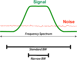
For clinical MRI the term "narrow bandwidth" typically means a setting in the range of 5-20 kHz. Since the distribution of noise is fairly evenly distributed across the entire frequency spectrum, limiting BW reduces the amount of noise mixed in with the signal. Thus, decreasing BW increases the signal-to-noise ratio (SNR) within the image. This is particularly advantageous for long echo time (TE) images and for other situations where the MR signal may be weak.
|
In spite of this SNR advantage, low bandwidth techniques with their longer sampling times should be used infrequently and with caution. First, longer sampling provides a longer window for unwanted spurious echoes to be detected. These may be manifest as rippling or zipper-like artifacts in the center of the image. The longer sampling window also gives more time for patient motion and flow artifacts to be generated. Secondly, chemical shift artifacts are accentuated using a narrow BW technique because a smaller band of frequencies spans each pixel. Similarly, magnetic field inhomogeneities and artifacts from ferromagnetic objects are accentuated. This may result in greater geometric distortion and greater slice-to-slice differences in size. Finally, more time spent collecting each echo limits the minimum TR, minimum TE, and maximum number of slices available for a given pulse sequence.
Variable bandwidth, also known as optimal bandwidth or matched bandwidth, is a practical compromise that can be performed on multi-echo studies. Here, regular or high BWs are used for early echoes, while smaller BWs are used for later echoes where the signal is weaker. This option is available on all major brands of scanners under slightly different names: from GE and Hitachi as "Variable Bandwidth (VB)", Siemens as "Optimized Bandwidth", Philips as "Optimized Water/Fat Shift", and Canon as "Matched Bandwidth".
Variable bandwidth, also known as optimal bandwidth or matched bandwidth, is a practical compromise that can be performed on multi-echo studies. Here, regular or high BWs are used for early echoes, while smaller BWs are used for later echoes where the signal is weaker. This option is available on all major brands of scanners under slightly different names: from GE and Hitachi as "Variable Bandwidth (VB)", Siemens as "Optimized Bandwidth", Philips as "Optimized Water/Fat Shift", and Canon as "Matched Bandwidth".
Advanced Discussion (show/hide)»
No supplementary material yet. Check back soon!
References
Graessner J. Bandwidth in MRI? MAGNETOM Flash 2/2013, pp 3-8. (very nice educational article available online at www.siemens.com/magnetom-world).
Graessner J. Bandwidth in MRI? MAGNETOM Flash 2/2013, pp 3-8. (very nice educational article available online at www.siemens.com/magnetom-world).
Related Questions
I know I was taught this in school, but can you briefly review the difference between phase and frequency?
What is bandwidth?
I know I was taught this in school, but can you briefly review the difference between phase and frequency?
What is bandwidth?


