Cardiac Implantable Electronic Devices (CIEDs) are designed to detect and treat disturbances in cardiac rhythm (arrhythmias). CIEDs include both Permanent Pacemakers (PPMs) and Implanted Cardioverter-Defibrillators (ICDs). PPMs deliver relatively mild shocks to the cardiac conduction system and are used primarily for treatment of slow heart rates (bradycardias). ICDs deliver high energy shocks for treatment of rapid heart rates (tachycardias).
Standard CIED Configurations
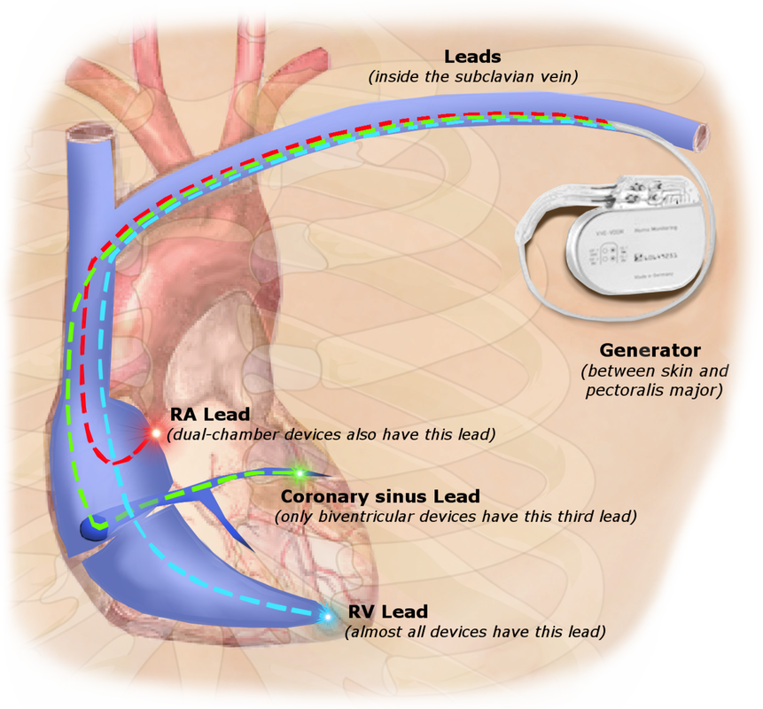
With the exception of a few uncommon "leadless" and epicardial devices described below, virtually all CIEDs contain the following elements:
- A pulse generator (PG), including a lithium-ion battery and electronics housed in a titanium "can", surgically implanted in the chest wall below the clavicle.
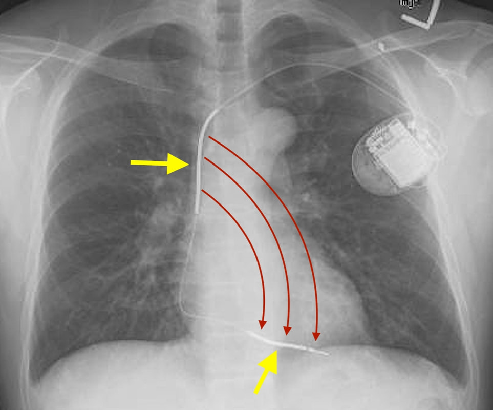
- 1-3 insulated wires leads passed fluoroscopically from the PG to the right heart via the subclavian vein and superior vena cava. Terminal electrodes are affixed to the myocardium by spiral wires or tines. Most modern terminal electrodes are bipolar, meaning they have two bare contact points near their tips, allowing focused sensing of the heart's local electrical activity and accurate delivery of pacing shocks as needed.
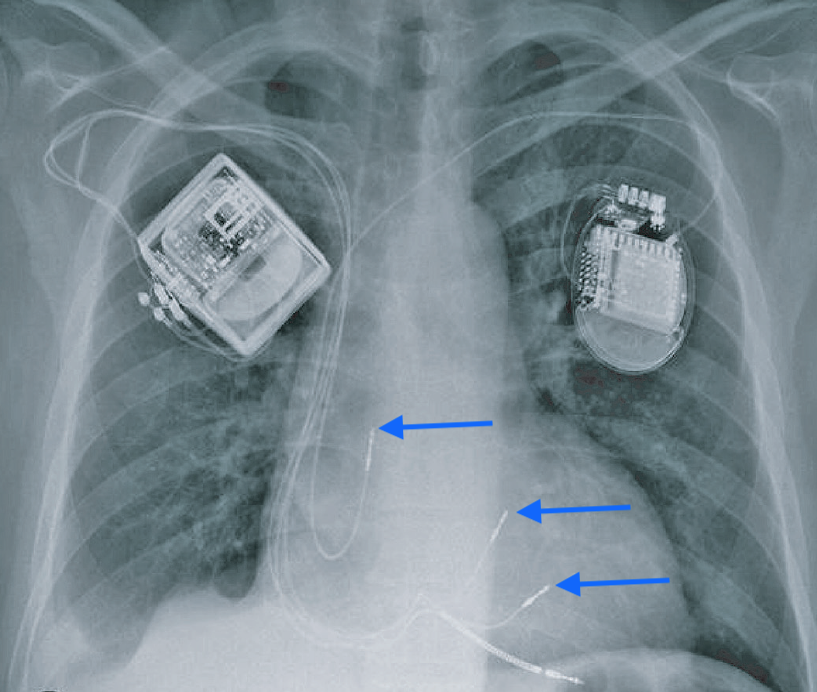
Single lead CIEDs typically terminate in the right atrial appendage or right ventricle. They are uncommon and primarily used for bradycardia due to sinus node dysfunction. The overwhelming majority of CIEDs contain two leads (one in the right atrium and one in the right ventricle) for dual-chamber sensing and pacing that follows the natural contraction sequence of the heart. Three-lead CIEDs are primarily used in patients with heart failure or left bundle branch block who require biventricular pacing. The third wire passes through the coronary sinus and into a coronary vein to simulate the left ventricle transvenously. This configuration is commonly referred to as Cardiac Resynchronization Therapy (CRT). Rarely additional leads are present for bundle of His or multisite pacing.
|
CIEDs that operate as high-energy ICDs demonstrate several differences compared to simple PMs. Their PGs are slightly larger, containing bigger batteries and capacitors for storing charge. They have large surface area electrodes known as shock coils located coaxially along the surface of the pace/sense leads. These shock coils are typically located in the right ventricle and also often in the superior vena cava. They can be recognized on x-ray as focal areas of wire thickening. Strong currents pass between the shock coils to depolarize the heart. Sometimes the housing of the PG functions as an additional current source, the so-called "active can" configuration.
|
Several terms are frequently encountered when discussing pacemaker function with regard to MRI:
- Asynchronous (fixed) pacing: A mode of operation where the PM delivers stimuli at a constant rate regardless of intrinsic cardiac signals.
- Synchronous (demand) pacing: A mode of operation where the PM delivers a stimulus after a certain time period if no expected cardiac signal is sensed.
- Pacing capture threshold: The minimum electrical stimulus measured in millivolts (mV) to consistently depolarize ("capture") the myocardium. This can increase over time as fibrosis builds at the electrode tip.
- Lead impedance: A measure of resistance to electrical flow within a lead measured in ohms (Ω). A break in the lead can dramatically increase impedance, while a defect in the insulation can result in a short with low impedance.
- Reed switch: an electrical component within older pulse generators that controls pacing mode and may open/close unpredictably in MRI.
NBG Codes for Pacemakers
The North American Society of Pacing and Electrophysiology and British Pacing and Electrophysiology
Groups (NBG) have jointly developed a coding system to describe various pacing modes. The full (revised) code contains 5 letters, but often only the first three are used.
Groups (NBG) have jointly developed a coding system to describe various pacing modes. The full (revised) code contains 5 letters, but often only the first three are used.
- The first letter indicates the chamber(s) paced: A=atrium, V=ventricle, or D=dual (both A&V)
- The second letter indicates in which chamber(s) electrical activity is sensed: A, V, or D. The letter O indicates no sensing is used.
- The third letter refers to how the PM responds to a sensed cardiac electric signal: T=triggered to give a shock, I= inhibited, D=dual response (any spontaneous A and V activity will inhibit both A&V pacing, but lone atrial activity will trigger a paced ventricular response), and O= no sensing.
- The fourth and fifth letters are used to denote rate modulation and multisite pacing and are only occasionally used.
Common operational modes include DDD (Atrial and ventricular sequential pacing, with pacing impulses triggered only when programmed intervals are exceeded), VVI (pure ventricular pacing whenever R wave is not detected), DOO (dual asynchronous pacing at constant rate regardless of intrinsic cardiac activity, and OOO (pacemaker disabled).
NBD Codes for Defibrillators
A shortened code by the same societies has been promulgated to reflect the common modes of ICD operation:
- ICD-S: An ICD with shock capability only
- ICD-B: An ICD with bradycardia pacing as well as shock
- ICD-T: An ICD with both tachycardia (and bradycardia) pacing as well as shock
Other Pacing Methods and Devices
- Temporary Transvenous Pacing is used primarily in emergency situations like acute profound bradycardia. A pacemaker wire is passed through the femoral or internal jugular vein into the heart, while the pulse generator remains outside the body. Due to the risk of significant lead heating demonstrated in animal models, these devices are considered MR Unsafe.
- Temporary Epicardial Pacing leads are placed in contact with the outer wall of the right heart at the end of open-heart surgery. The wires then extend percutaneously through the chest wall where they are hooked to a small battery-powered pulse generator. The wires are usually removed within a few days to weeks after the patient's postoperative rhythm disturbances have subsided.
- Permanent Epicardial Pacemakers are used occasionally in pediatric patients with complex congenital heart disease. The pulse generator is typically placed subcutaneously in the upper abdominal wall.
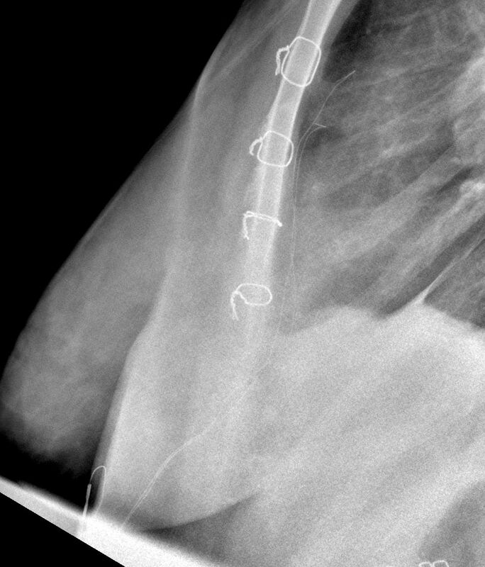
Temporary epicardial pacing wires
Case courtesy of Dr Jeremy Jones, Radiopaedia.org. |
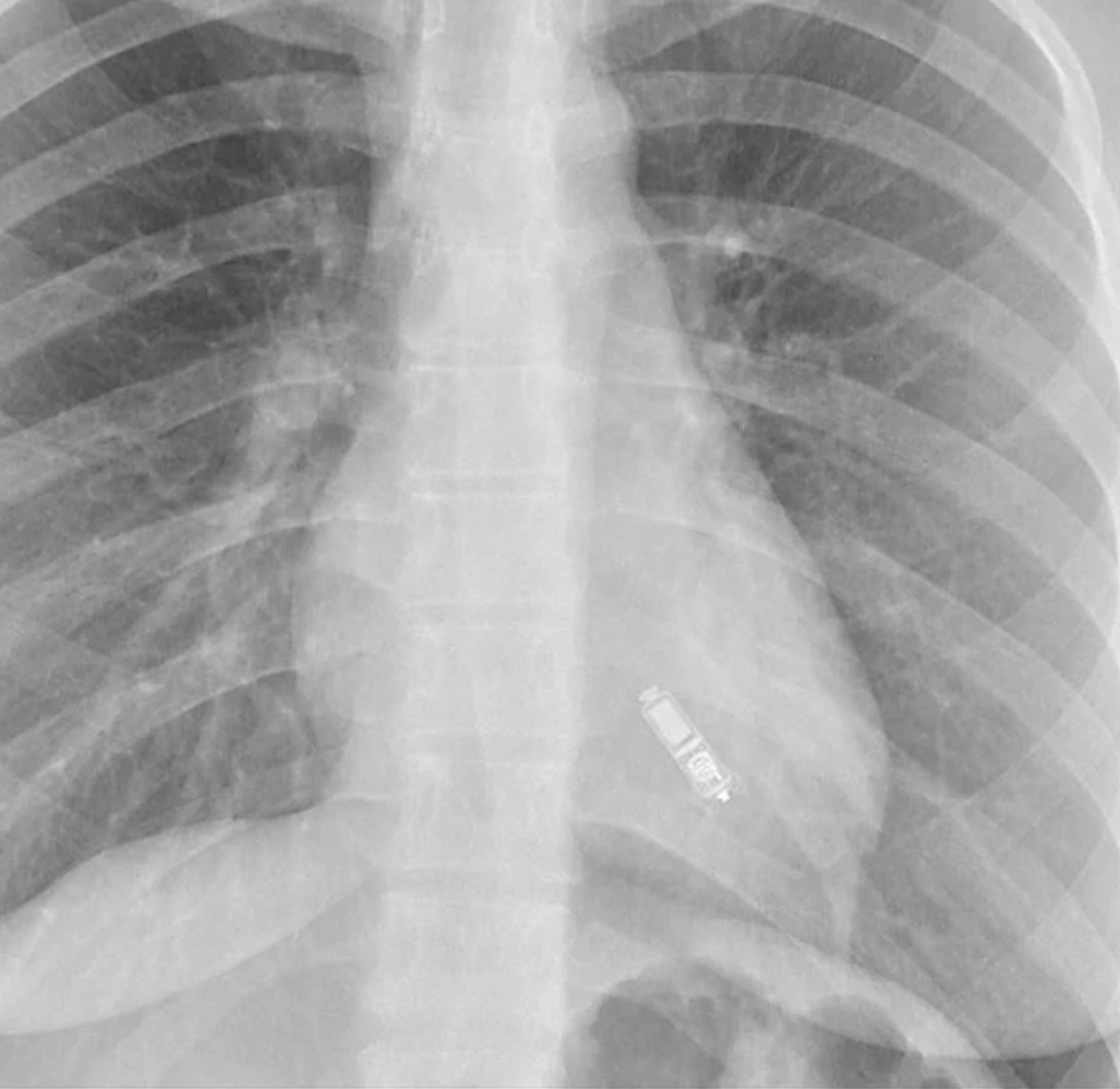
- Leadless RV Pacemakers are small, self-contained devices implanted fluoroscopically into the right ventricular endocardium, exemplified by the MR Conditional Nanostim™ (Abbott) and Micra™ (Medtronic). Internal accelerometers allow them to partially sync with right atrial contraction, but essentially they only sense and pace the RV. Because of their small size, they are unable to deliver high-energy shocks for tachyarrythmias.
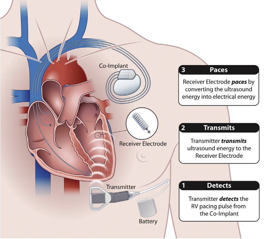
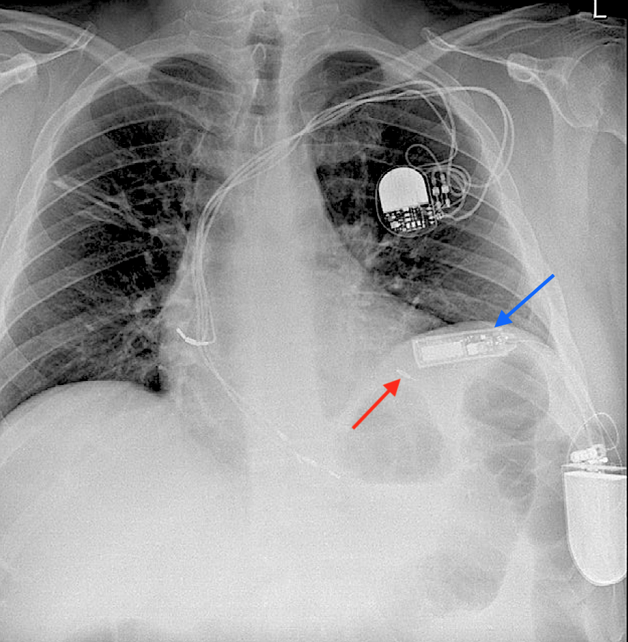
- Leadless LV Pacemakers. Only one such device, the MR Conditional WiSE-CRT System (EBR Systems), is commercially available (Europe only). A tiny (3 x 9 mm) passive electrode-transponder is fluroscopically implanted in the left ventricular endocardium. It converts ultrasound pulses received from a separate subcutaneous generator into electrical stimuli, thus triggering the ventricle. The entire system is not really leadless, since a conventional (wired) dual chamber pacemaker is required to control the right side of the heart.
- Cardiac Contractility Modulators (CCM). At present there is only one commercial product in this category, the Optimizer™ (Impulse Dynamics), used for patients with refractory heart failure. Resembling a conventional pacemaker, the device is subcutaneously implanted in the subclavicular region with two wires to stimulate the right ventricle. Pulses from Optmizer™ given in four daily 1-hour sessions "exercise" the heart, presumably leading to improved cardiac function. This MR Conditional device requires recharging weekly by an external induction coil.
- Subcutaneous ICDs have shock coils implanted in the anterior chest wall rather than in or on the heart, with the pulse generator can serving as the anode. The main device in this category is the MR Conditional Emblem™ S-ICD (Boston Scientific). S-ICDs may be devices of choice for young patients or those at risk for intravascular thrombosis.
MRI safety issues concerning conventional CIEDs as well as these other devices are the subject of the next several Q&As.
Advanced Discussion (show/hide)»
No supplementary material yet. Check back soon!
References
Bhatia N, El-Chami M. Leadless pacemakers: a contemporary review. J Geriatric Cardiol 2018; 15:249-253. [DIRECT LINK]
Bernstein A, Camm A, Fisher J, et al. North American Society of Pacing and Electrophysiology policy statement. The NASPE/BPEG defibrillator code. Pacing Clin Electrophysiol 1993; 16:1776–80.
Bernstein AD, Daubert J-C, Fletcher RD, et al. The revised NASPE/BPEG generic code for antibradycardia, adaptive-rate, and multisite pacing. Pacing Clin Electrophysiol 2002; 25:260-264.
Costa R, da Silva K, Filho MM, Carrillo R. Minimally invasive epicardial pacemaker implantation in neonates with congenital heart block. Arq Bras Cardiol 2017; 109:331-339.
Mulpuru SK, Madhavan M, McLeod CJ, et al. Cardiac pacemakers: function, troubleshooting, and management. J Am Coll Cardiol 2017; 69:189-210. [DOI LINK]
Mulpuru SK, Madhavan M, McLeod CJ, et al. Advances and future directions in cardiac pacemakers. J Am Coll Cardiol 2017; 69:211–35. [DOI LINK]
Sieniewicz BJ, Betts TR, James S, et al. Real-world experience of leadless left ventricular endocardial cardiac resynchronization therapy: A multicenter international registry of the WiSE-CRT pacing system. Heart Rhythm 2020; 17:1291-7. [DOI LINK]
Sperzel J, Burri H, Gras D, et al. State of the art of leadless pacing. Europace 2015; 17:1508-1513.
Related Questions
Do pacemakers stop working in an MRI scanner? Why are older pacemakers dangerous to scan?
Do pacemakers stop working in an MRI scanner? Why are older pacemakers dangerous to scan?
