|
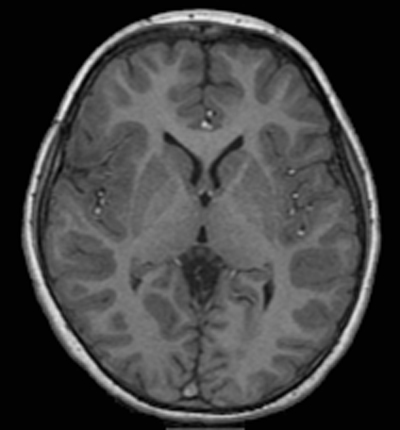
Because the spoiled-GRE technique is specifically designed to disrupt transverse (T2) coherences, its major benefit and use is in producing T1-weighted images. Nevertheless, both spin density- and T2*-weighting can be achieved by appropriate selection of parameters. As a result of this versatility and the ability to acquire images in either 2D or 3D modes, spoiled-GRE sequences are now ubiquitously used for MR imaging of virtually every body part.
|
The signal from a spoiled-GRE sequenced depends on three operator-selectable parameters (TR, TE, and flip angle α) plus three intrinsic tissue parameters (T1, T2*, and spin-density [H]). Note that dependence is on T2* rather than T2 because SE/STE formation is suppressed by spoiling and the signal is generated by gradient refocusing of an FID.
Assuming a longitudinal steady-state has been reached and perfect spoiling, the signal (S) of a spoiled GRE sequence is given by
where k is a scaling factor. By simple calculus (setting dS/dα = 0) we find that the the signal is maximized when α = αE, the Ernst angle, where
The Ernst angle concept has already been introduced in a previous Q&A to which the reader is referred for more details. It should be noted that although the Ernst angle gives the highest signal for a given tissue for a certain TR/T1 combination, it does not necessarily maximize image contrast between two different tissues.
Carefully dissecting the signal equation provides insight into parameter weighting. Specifically,
 Click to enlarge
(1) Signal is always proportional to spin density [H], an effect that can never be removed.
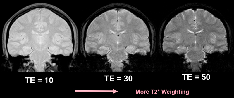
(2) TE controls T2*-weighting. The only place T2* appears in the equation is in the final term [exp (−TE/T2*)]. When TE is large, this term dominates. When TE is small, this term approaches unity and the T2* contribution is minimized.
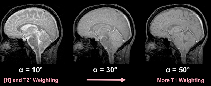
(3) Flip angle (α) controls T1-weighting. A small flip angle minimizes T1-weighting because the longitudinal magnetizations of various tissues are not differentiated much by such a small angular displacement. Hence at small flip angles, [H] and T2* effects predominate. Conversely, as α → 90º, T1-weighting increases.
(4) TR controls T1-weighting. Note that all occurrences of TR in the equation are in terms of the form [exp (−TR/T1)]. When TR is small, this term becomes large and T1-weighting increases. Conversely, when TR is long, T1-weighting is minimized.
The effects of TE, α, and TR on image contrast are summarized in the images montages below:
|
Effect of Flip Angle (α) α controls T1-weighting |
A small flip angle (α) minimizes T1-weighting. This is because a small flip angle only changes the steady-state longitudinal magnetization of various tissues slightly. Hence they are only slightly differentiated based on their intrinsic T1 properties. So at low flip angles, [H] and T2* effects predominate. Conversely, as α → 90º, T1-weighting increases.
|
A table providing typical spoiled GRE-parameters to achieve different contrast weightings applicable for 1.5T is given below:
Advanced Discussion (show/hide)»
No supplementary material yet. Check back soon!
References
Buxton RB, Edelman RR, Rosen BR et al. Contrast in rapid MR imaging: T1- and T2-weighted imaging. J Comput Assist Tomogr 1987; 11:7-16.
Elster AD. Gradient echo imaging: techniques and acronyms. Radiology 1993; 186:1-8.
Ernst RR, Anderson WA. Application of Fourier transform spectroscopy to magnetic resonance. Rev Sci Instrum 1966; 37:93-102. (Fairly heavy math, but a classic)
Haase A, Frahm J, Matthaei KD. FLASH imaging: rapid NMR imaging using low flip angle pulses. J Magn Reson 1986: 67: 258-266.
Winkler ML, Ortendahl DA, Mills TC, et al. Characteristics of partial flip angle and gradient reversal MR imaging. Radiology 1988;166:17-26.
Related Questions
What is meant by spoiling, and how is it accomplished?
What is meant by spoiling, and how is it accomplished?


