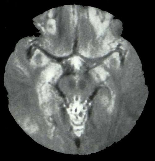
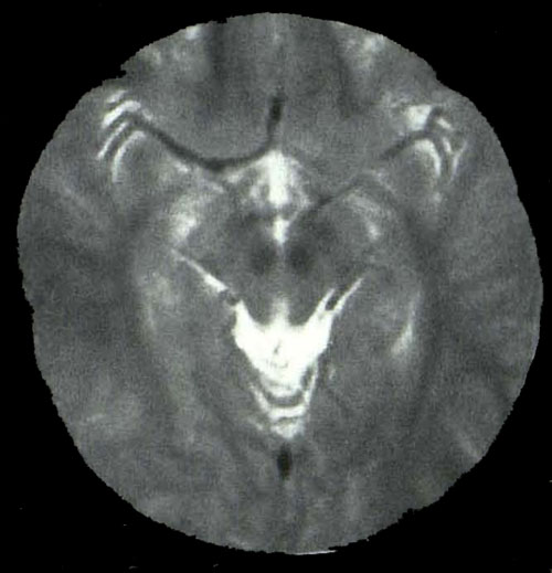
The idea of adjusting the waveforms of imaging gradients to correct for flow-related dephasing was first implemented by Picker scientist Fred Pattany working at Wake Forest in the late 1980's. The original technique was known as MAST (Motion Artifact Suppression Technique) proved immediately useful for suppressing artifacts and improving quality of MR images.
Other vendors quickly followed suit, creating similar pulse sequences that became generically known as "flow compensation" or "gradient-moment nulling". Today these methods are known by various trade names: Siemens (GMR = "Gradient-Moment Rephasing"), GE ("Flow Comp"), Philips (FLAG = "FLow Adjusted gradients"), Hitachi (GR - "Gradient Rephasing"), and Canon (FC = "Flow Compensation").
|
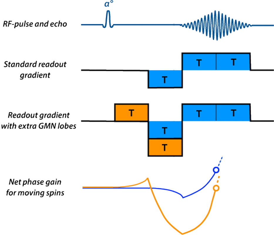
In gradient-moment nulling, additional gradient lobes are added prior to signal readout to compensate in advance for motion-induced dephasing at the time of the echo. As a simple example, let us analyze the velocity-compensated GRE sequence shown right. Note that the readout gradient has a more complex appearance than in the usual GRE sequence, with the addition of the two orange lobes. These additional gradient lobes give this sequence its flow-compensation properties.
|
For stationary spins, the additional orange gradient lobes have no net effect, each adding or subtracting a constant amount of phase. Since there are two positive-going and two negatively-going lobes before the center of the echo, their net effect is zero.
The net phase changes for spins moving at constant velocity are shown in the lower portion of the diagram. Using the standard GRE readout gradient, moving spins accumulate phase that is nonzero at the center of the echo (blue circle). This non-zero phase at mid-echo results in signal loss.
These two extra GMN lobes play a clever little game with the phase. The first orange lobe creates a phase gain, but the second orange lobe during the next time interval, when added to the phase changes from the first blue lobe, create a strongly negative phase loss. By the middle of readout, however, the net phase of the moving spins using GMN has returned to zero (orange circle).
These two extra GMN lobes play a clever little game with the phase. The first orange lobe creates a phase gain, but the second orange lobe during the next time interval, when added to the phase changes from the first blue lobe, create a strongly negative phase loss. By the middle of readout, however, the net phase of the moving spins using GMN has returned to zero (orange circle).
This is a very simple illustration using a GRE sequence, but the same method may be applied to other pulse sequences and imaging axes. For example, GMN can be performed along the slice-select direction as well as along the readout direction. It can also be extended to correct for higher orders of motion, such as constant acceleration.
The principal limitations of GMN techniques are: (1) they correct only for motion at constant velocity or acceleration; (2) the minimum TE is lengthened because time is needed to fit in the extra gradient lobes; (3) stresses on the imaging gradients are increased, potentially limiting field-of-view or slice thickness for a given TR; and (4) artifacts caused by eddy currents may be induced by the rapid gradient switching required.
For a more quantitative description of how GMN works, click on the Advanced Discussion tab or check one of the references below.
Advanced Discussion (show/hide)»
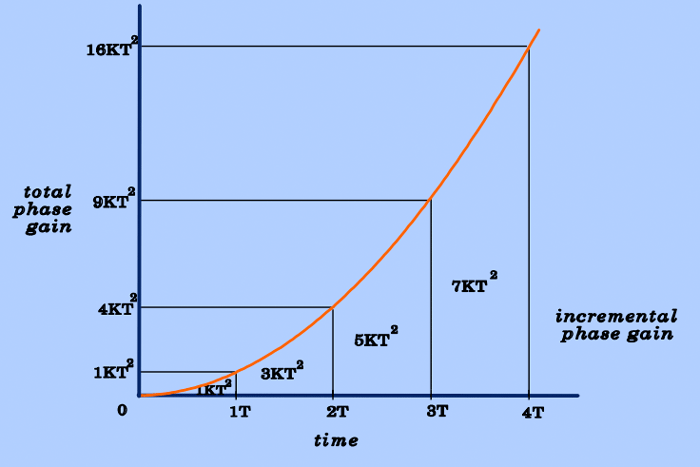
To explain how gradient-moment nulling works, it is necessary to make use of a fact developed in the Advanced Discussion section of the prior Q&A on Even-Echo Rephasing. Here we showed that for constant velocity flow (v) through a constant gradient (G), total phase shift (Φ) increases quadratically with time (T). In other words
Φ = KT²
where K = ½ γ G v is a constant when velocity and readout gradient strength are also constant.
This quadratic dependence of total phase gain upon time is shown in the figure below. Note that after 1, 2, 3, and 4 gradient intervals each of duration T, the phase has increased quadratically to KT², 4KT², 9KT², and 16KT² respectively. The incremental phase contributions of the 1st, 2nd, 3rd, and 4th gradient intervals are therefore KT², 3KT², 5KT², and 7KT², respectively.
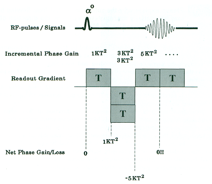
Let us now consider in a more quantitative way the first-order gradient-moment nulling pulse sequence previously diagrammed..
To analyze what happens to a spin moving at constant velocity, we will do an incremental phase calculation similar to that performed for the even-echo rephasing case. After the first block, the phase should again be KT². The incremental phase contribution from the two blocks that compose the second lobe is 2 x (−3KT² = −6KT². The net phase of the moving spins immediately after the double block is therefore KT² −5KT² = .−5KT². Finally, the first readout block contributes its incremental +5KT², yielding a net phase of zero at t = TE. By adding these extra gradient blocks, we have compensated or corrected for phase dispersions attributable to constant velocity.
The above example describes first-order (velocity) gradient-moment nulling. The method can be easily extended by to compensate for phase dispersions due to second-order (acceleration), third-order ("jerk"), and even higher degrees of motion. These higher order corrections require more gradient lobes (specifically, n+1 additional lobes, where n = motion order to be compensated). These extra lobes take time to play out, so using higher order GMN even further lengthens minimum TE and reduces number of slices for a given TR. Also, the effectiveness of the method decreases as the order increases. In practice, therefore, velocity-compensated GMN is nearly exclusively used, with acceleration-compensated GMN performed only occasionally.
References
Elster AD. Motion artifact suppression technique (MAST) for cranial MR imaging: superiority over cardiac gating for reducing phase shift artifacts. AJNR Am J Neuroradiol 1988; 9:671-674.
Haacke EM, Lenz GW. Improving MR image quality in the presence of motion by using rephasing gradients. AJR Am J Roentgenol 1987; 148:1251-1258.
Pattany PM, Phillips JJ, Chiu LC, et al. Motion artifact suppression technique (MAST) for MR imaging. J Comput Assist Tomogr 1987; 11:369-377.
Richardson DN, Elster AD, Williams DW III. Gd-DTPA-enhanced MR images: accentuation of vascular pulsation artifacts and correction using gradient-moment nulling (MAST). AJNR Am J Neuroradiol 1990; 11:209-210.
Related Questions
Can you explain even-echo rephasing?
Can you explain even-echo rephasing?
