Accuracy of each of these measurements can be determined using test phantoms as described below. As for most quality metrics, the American College of Radiology (ACR), American Association of Physicists in Medicine (AAPM), and National Electrical Manufacturers Association (NEMA) publish detailed procedures for each of these (available from the References below).
Laser Alignment and Table Position
|
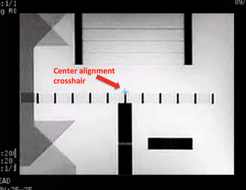
Before performing any slice or geometric measurements, the phantom should be placed in a head holder or other stable device and perfectly squared to the scanner bore using a bubble level. The table is then advanced and so that the patient alignment laser falls on the external landmark representing the phantom's exact center. After pressing "Advance to Scan" (or a similar button) the table and phantom will be moved into the magnet's isocenter. A sagittal scan of the phantom at this time will reveal a set of alignment bars whose positions can be measured with a cursor to verify accuracy of the laser-table position system.
|
Slice Thickness and Profile
|
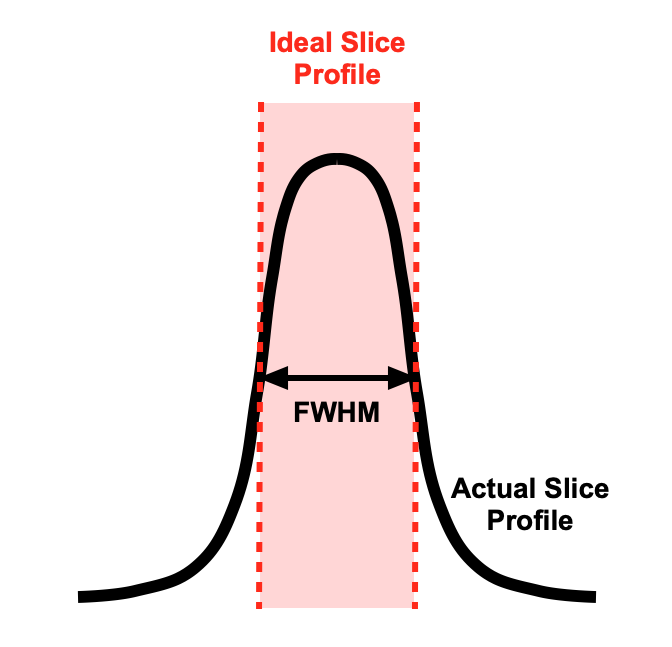
The first thing to recognize is that slices in MRI are constructed from a limited number of Fourier frequency components and hence are never perfectly rectangular. They have a bell-curve profiles with wider bases and narrower central peaks. Slice thickness is defined as the full width at half maximum (FWHM) signal intensity as shown in the diagram left.
The most common method to estimate slice thickness is to use a phantom containing triangular ramps or wedges whose surfaces are oriented at a known angle (θ) to the plane of the slice. When a slice passes through the ramp, it produces a stretched "shadow" image whose FWHM can be estimated. The slice thickness (THK) is then:
|
|
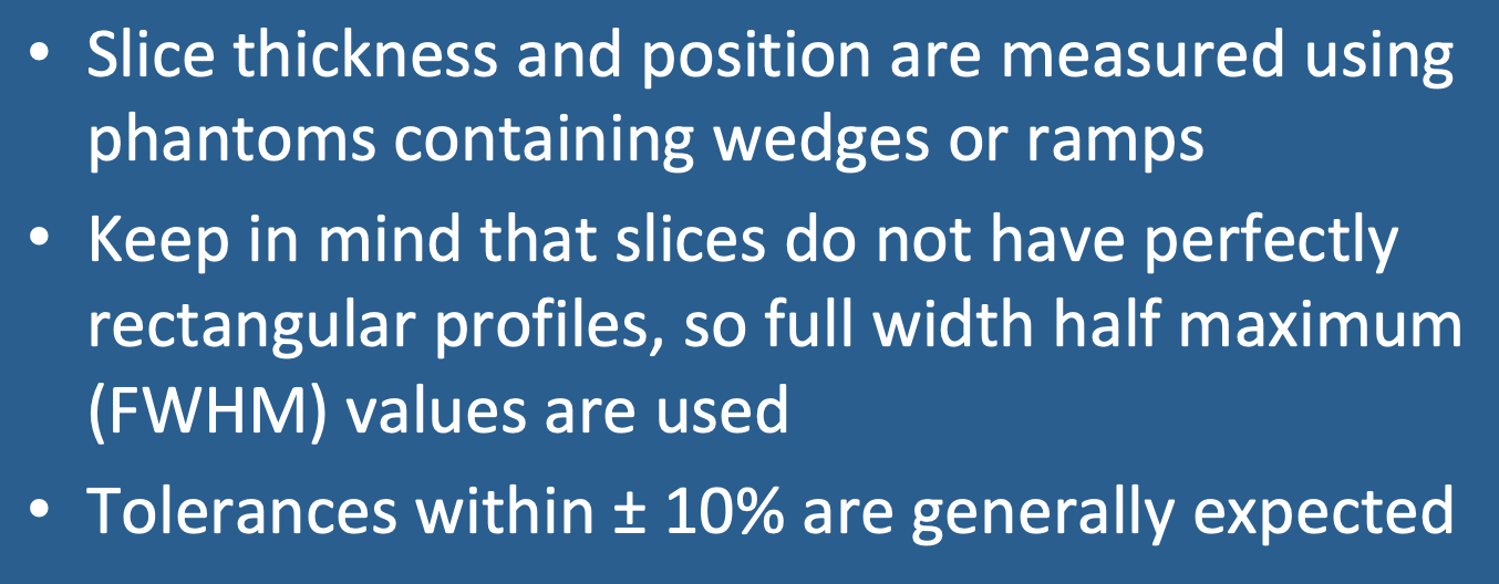
Slice thickness tolerances should generally be less than ±10% on a well-functioning scanner (although the ACR allows up to ±20% and still meet accreditation).
The usual cause of slice thickness failure is RF-amplifier non-linearity with distorted pulse shapes. Other causes include problems anywhere else along the RF transmission chain, including cables, switches, and coils. All require troubleshooting by an MR service engineer.
|
Slice Position
 Use of opposing ramps in a phantom to determine slice position accuracy.
Slice position accuracy tests how well the actual locations of slices differ from their prescribed locations. The standard method uses two oppositely-directed wedges. A slice passing through the exact center of overlap should result in two bars of nearly equal length in the phantom image. If the slice is malpositioned off-center, the two bars will be unequal in length.
As for slice thickness measurements, slice positioning should ideally be within ±10% tolerance limits. Slice position inaccuracies most frequently arise from operator error, table position/laser malalignment, bad gradient calibration, or poor Bo inhomogeneity.
Advanced Discussion (show/hide)»
The most accurate methods for slice thickness measurements are well-described in the accompanying link to NEMA MS 5. Ideally two ramps or wedges should be used and corrections made for their slight misalignment or rotation. Determining the FWHM from the “shadow” image” of the phantom is not trivial. An edge response function (ERF) of signal intensity is first obtained, then differentiated with respect to position to obtain slice profile and FWHM.
References
American Association of Physicists in Medicine (AAPM). Report No.100. Acceptance testing and quality assurance procedures for magnetic resonance imaging facilities. 2010.
American College of Radiology. Phantom test guidance for use of the large MRI phantom for the ACR accreditation program, 2018.
National Electrical Manufacturers Association. NEMA Standards Publication MS 5-2008 (R2014). Determination of slice thickness in diagnostic magnetic resonance imaging. NEMA, Washington, DC. Can be downloaded for free or purchased in book form here.
Related Questions
What types of routine quality control must be performed on an MR scanner?
What is cross-talk and what can be done about it?
What types of routine quality control must be performed on an MR scanner?
What is cross-talk and what can be done about it?


