|
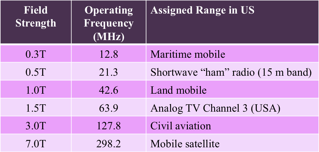
MRI involves the absorption and emission of energy by nuclei at a specific resonant (Larmor) frequency. The Larmor frequency scales directly with main magnetic field strength (Bo), and for clinical MRI lies in the range of tens to hundreds of MHz. These frequencies are part of the electromagnetic spectrum commonly used for radio transmission.
|
For MRI a time-varying radiofrequency (RF) field, commonly referred to as B1, must be first transmitted into the spin system near the Larmor frequency. In addition to having specific frequency, the B1 field must also be applied perpendicular to the main magnetic field (Bo). The B1 field is produced by driving electrical currents through specialized RF-transmit coils. These coils are located either within the inner walls of the scanner or as free-standing devices connected by cables placed on or near the patient.
A sophisticated electronic "RF-front end" is responsible for generating, shaping, and amplifying the electrical currents required to produce the B1 field. The basic components in this RF-transmit chain are:
A sophisticated electronic "RF-front end" is responsible for generating, shaping, and amplifying the electrical currents required to produce the B1 field. The basic components in this RF-transmit chain are:
Frequency Synthesizer → Modulator → Amplifier → Quad Hybrid → T/R Switch → Coil
Frequency synthesizer. This component produces a continuous sinusoidal carrier wave at (or near) the Larmor frequency. Driven by a quartz crystal, the synthesizer utilizes a numerically controlled oscillator (NCO) monitored by a phase-locked loop (PLL) to maintain precise digital control over frequency and phase. The output from the synthesizer will be sent two places simultaneously: 1) further down the RF-transmitter chain to the pulse modulator for shaping; and 2) into the RF-receiver chain where it will be used as a reference for demodulating/decoding the MR signal.
|
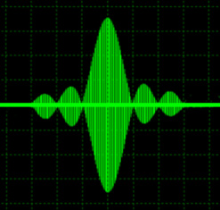
Pulse modulator. The B1 fields used in nearly all clinical MR imaging applications are not transmitted as continuous waves, but in short (1-5 ms) bursts, called RF-pulses. The continuous carrier wave from the frequency synthesizer must therefore be "chopped up" into small pieces and these pieces appropriately "shaped" into pulses as dictated by the particular imaging application. The contours of each RF-pulse are specified using 100-200 data points, and are therefore of low-frequency (measured in kHz). The pulse-shape data is used to modulate the carrier wave so that the resultant output is a mixture of frequencies centered around the carrier.
|
|
High Power Amplifier. The newly fashioned RF-pulse next passes through a high-power amplifier that generates the large currents necessary to drive the RF-coils. The amplifiers used in modern MR systems typically produce peak power in the range of 10-30 kW resulting in maximum transmitted B1 fields on the order of 10-50 μT. The gain of the power amplifiers is adjusted by an active circuit element called the transmit attenuator. By changing the degree of RF attenuation (or alternatively, its gain/amplification) the flip angle of the RF pulse is adjusted. The terminology and measurement units differ by manufacturer , being variously referred to as transmit attenuation, transmit gain, RF gain, reference amplitude, RF level, or RF drive scale. Regardless of name, monitoring RF gain/attenuation is an important part of regular quality control to insure the scanner transmitter chain elements are working properly.
Quadrature Hybrid Coupler. The output of the power amplifier is typically split into two equal parts by means of a quadrature hybrid coupler device. The resultant outputs are 90° out of phase with one another and are used to feed the two ports of the quadrature transmit coil. The two outputs of the coupler are commonly known as I and Q, standing for "in phase" and "quadrature" respectively.
Transmit/Receive (T/R) Switch and Coil. The currents in the I and Q outputs of the coupler is now headed for the RF-transmitter coils. As scanners may have several possible transmitter coils, electronic switching circuitry is necessary to make sure that current is delivered to the proper coil at the proper time. Additionally, sometimes the same coils are used to both transmit B1 and receive the MR signal. For these coils a special T/R switch is required to isolate the two functions and make sure the powerful electric currents used for transmission do not go into and burn up the sensitive receiver circuitry.
Advanced Discussion (show/hide)»
Although RF-coils transmit electromagnetic radiation in the range of "radio waves", the emitted MR signal is not itself a conventional radio wave. (See the excellent but highly technical discussion in Hoult DI. The origins and present status of the radio wave controversy in NMR. Concepts Mag Reson Part A 2009;34A(4):193-216.) It is OK to talk about radio frequencies, but probably not radio waves.
References
Introduction to NMR/MRI amplifiers. CPC Amps, Inc. 2012.
Spectrum Wiki Website. Just type in the frequency of interest and this site will tell you how it is used world-wide.
Introduction to NMR/MRI amplifiers. CPC Amps, Inc. 2012.
Spectrum Wiki Website. Just type in the frequency of interest and this site will tell you how it is used world-wide.
Related Questions
What are the function(s) of radiofrequency (RF) coils?
What are gradient coils?
How do RF-transmit coils work?
Isn't the MR signal just re-emission of absorbed radio waves?
What are the function(s) of radiofrequency (RF) coils?
What are gradient coils?
How do RF-transmit coils work?
Isn't the MR signal just re-emission of absorbed radio waves?


