The RF Subsystem: MR Signal Conversion/Detection
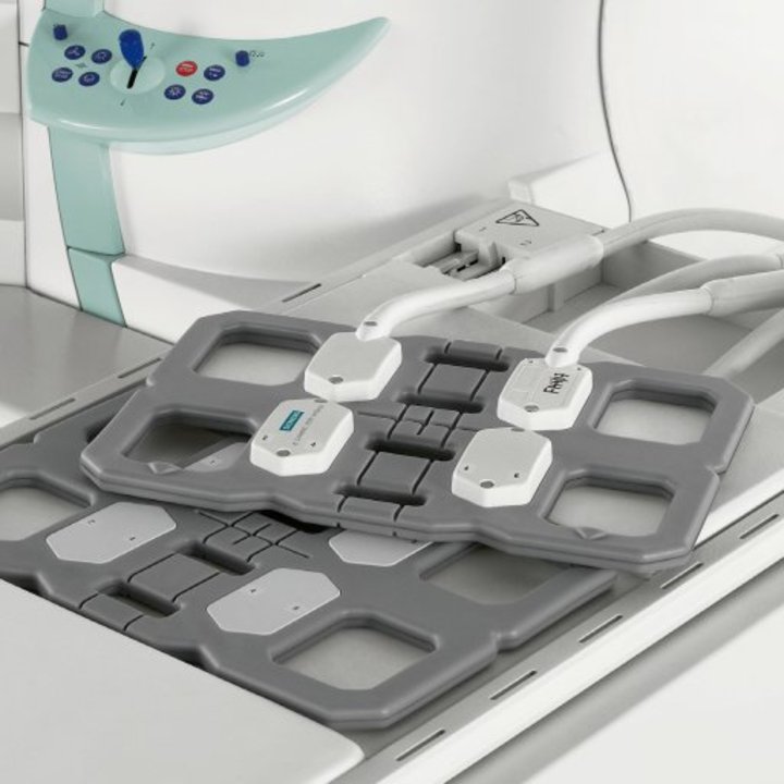
The RF-receiver coil is the first element of a complex electronic chain by which the MR signal is amplified, digitized, decoded, and transferred to the main computer system for processing into the final MR image.
The detected MR signal shares several features with the transmitted RF-pulse: 1) Both contain a carrier wave centered at the Larmor frequency; 2) important imaging information (position, intensity, etc) is modulated into the carrier wave; 3) a chain of electronic elements must be used to amplify, digitize, and decode the information.
The basic components of the RF-receiver chain are:
Coil Decoupling → Preamplification → ADC → Demodulation → Image Processing
Decoupling. During the nuclear stimulation phase of MRI, large amounts of power (exceeding 10 kW) at the resonant frequency are transmitted into the magnet bore by the B1 field. The RF receiver coils and associated circuitry that will ultimately detect the emitted MR signal are tuned to this same frequency. To prevent the coils from being burned out by the powerful RF pulses, they are electronically “detuned” or "decoupled" briefly during RF transmission.
|
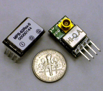
Preamplification. The MR signal detected by the RF coil is extremely weak (on the order of millivolts). To prevent contamination by environmental noise, the signal is immediately amplified close to the RF coil by a device called a low-noise preamplifier (also called an LNP or “preamp”). In most current (but older) systems, this amplified analog signal is then sent via long shielded cables from the scanner into an RF-processing unit in the adjacent equipment room where it is digitized. The newest MR systems employ small high frequency analog-to-digital converters (ADCs) in close proximity to the coils and send the digitized data to the next room via fiber-optic cables.
Analog-to-digital Conversion (ADC). In recent years considerable advances in analog-to-digital signal conversion have occurred thanks to cellular phone technology. Specifically, low-power, compact ADCs are now available allowing direct digital sampling of signals in the frequency range of MRI (~100 MHz) at depth exceeding 16 bits. The ADCs in many older systems are not as fast, requiring an additional step of down-conversion of the analog signal to lower intermediate frequencies prior to sampling. Most newer systems, however, are employing high-frequency direct digital conversion, and so the older down-conversion methods should be phased out over the next several years. |
|
Demodulation. As described in related Q&A's, all the important information for imaging is "hidden" within the RF-carrier wave. The MR carrier wave is both amplitude-modulated (AM) and phase-modulated (PM). Signal intensity is contained in the AM portion; spatial location in the PM portion of the wave. This embedded information is extracted through the process of demodulation. The demodulating circuitry receives a clean copy of the carrier wave directly from the RF synthesizer, which it mixes with the MR signal to extract the useful information. Low pass filters remove the high frequency carrier wave components. This demodulation process results in two channels (called I and Q) which represent the real and imaginary components of imaging information. This data is then sent forward to the image processing computers for reconstruction into the final MR image.
Advanced Discussion (show/hide)»
The above discussion applies to receive-only RF coils. When transmit-receive RF-coils are used, some additional and slightly different hardware is required related to the transmission phase (where energy is applied directly to the coil). First, a hybrid coupler must be used to distribute input power equally among the various coil ports. Next, a transmit-receive (T/R) switch is needed that directs power through the antenna coils only during transmission but permits current to flow through the detector/amplifier chain during reception. The T/R switch is necessary to prevent the high power transmission energy from burning out the receiver electronics circuitry.
References
Possanzini C, Harvey PR, Ham K et al. dStream architecture: the digital revolution in MRI (pdf). Philips Medical Systems, 2011. (A sales brochure, but gives a good explanation of advances in direct digital RF architecture now being used by many vendors).
Scarlett J. Advancements in MRI architectures reduce design complexity while improving image quality (pdf). Analog Devices Technical Article MS-2058, www.analog.com, 2010.
Reykowski A. Overview of signal detection and the RF chain (pdf). Presented at ISMRM 2006.
Related Questions
How do receive-only coils work?
How do receive-only coils work?

